 Image by Freepik
What is the difference between KBL and VEC?
Why should I use the VEC?
What are the benefits?
Do I really need it?
This whitepaper tries to provide fact based information about the history of both, the origins and their differences and to enable the reader to form his or her own opinion. But beforehand it should be said, the VEC is much more than just a KBL 3.0.
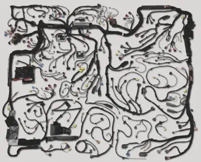
But, before we dive into the differences of both, let’s have a short look at their common subject: the wiring harness. The development of wiring harnesses can be characterized with one sentence:
Complexity is King!
The complexity is inherent, omnipresent and mainly driven by three factors:
- Technical Complexity: Created by new technologies, increasing number of E/E components and electrical functions in a vehicle.
- Variance: Modern vehicles are highly individualized, often customer specific. The pressure to optimize the wiring harness regarding weight, space and cost, results in a high representation of this variance in the physical wiring harness.
- Process: Short time-to-market requirements, high change rates and cross-organizational supply chains add additional complexity.
With that in mind, it is easy to understand that a high level of tool support and the avoidance of redundant activities in the development process provide a substantial advantage. Unlocking such potential was and is of great interest to the industry as a whole.
History and Scoping
To understand the differences between KBL and VEC, one needs to know the context for which both were created and which application scenarios were the drivers for their development.
The Beginning of a Journey
Before the turn of the millennium, the harness drawing was used as the primary medium in the communication between OEM and Supplier. This interface is a decisive point in the process. On the one hand, the world of product engineering is left and the world of manufacturing is entered; on the other hand, company boundaries are crossed. In either way, there is a significant change of the respective IT system landscape.
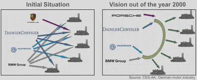
For a complex product like the wiring harness, a plain drawing, even a “digital1” one, tells only half the truth. If additional information was provided (e.g. bill of material, connectivity list) it was either inserted into the drawing as a table, or provided in other proprietary formats (e.g. text based record formats), or both. If such a product specification now switches the organizational context, it is easy to imagine that such media discontinuities lead to frequent manual data entry and associated problems such as loss of time and susceptibility to errors. This is further aggravated if the exchange of information is designed individually for each OEM-supplier relationship (see figure 1 - “Vision for the KBL in 2000”).
These learnings led to a paradigm shift in the development process, away from the creation of a plain, albeit digitally generated, drawing towards a more meaningful digital product specification, which in turn led to a generational change in the software solutions, and this is the point where the KBL saw the light of day with the following vision of its creators:
“We (OEM & Supplier) want to exchange the product specifications for the wiring harness completely, 100% electronically evaluable, standardised and openly.”
Ultimately, with the goal to a achieve a digital manufacturing specification (“Build-To-Print”). The result of this joint effort in the German Automotive Industry was the KBL, with its mission:
Provide a standardized data model for exchanging a product specification of a single wiring harness between OEM and Supplier.
However, since a picture is worth a thousand words, the scope of KBL is best described by figure 2.
Why KBL was only the Beginning, but not the End
Providing such a standardized data model for one of the major interfaces in the wiring harness development and production process was a big achievement. However, this was not the end, but just the beginning of an even bigger challenge.
Figure 3 shows a simplified generic version of the wiring harness development process as it might be implemented at any OEM. The development of wiring harnesses, or rather the development of the physical wiring system of an entire vehicle, is a cross-disciplinary task that depends on the information from a wide variety of process partners and meanwhile has to provide at least as many with information about itself. The KBL was intended to provide the manufacturing process with information about the harness itself, which is an important part, but also only a part of the complete picture (as highlighted in figure 3).

On the one hand, this restriction of the scope brings the advantage of being able to develop a relatively simple data model, in a short period of time, which has been desperately needed at that time. But on the other hand it also brings with it various limitations and restrictions:
- The content of the KBL is limited to a single harness. There is no possibility to have an integrated view on the physical wiring system of an entire vehicle. This means, for example, that the KBL does not contain any concepts for the representation of interfaces between wiring harnesses or the repeated use of the same harness (e.g. left & right door) in a vehicle, to name just two of the potential issues.
- The design of the KBL is focused on the manufacturing process as the primary information consumer. There are facts about the physical wiring system that are not relevant in a manufacturing process that allow simplifications, which are not valid in a broader scope.
- The KBL does not know anything about the electrical function implemented by the harness.
- There is only very limited information about the individual components used to create the wiring harness. Ultimately, it is limited to the information necessary to uniquely identify the component in a PDM world (part number) and for the actual product itself (colours, cable cross-sections, cavity numbers etc.).
- Some information required in the harness development process is not contained at all (e.g. E/E-Architecture, System Schematics, Electrical Interfaces of ECUs).
- Maintaining traceability across the different levels of the product development is difficult. Either because the connecting points are not included at all, or because the levels of abstraction are not congruent.
- It represents a snapshot of the development for single point in time.
These facts led relatively quickly to the realization that a more comprehensive solution was necessary in order to cover the data demands of the harness development process itself and to be able to serve process partners with more extensive data demands. This was the beginning of the development of the VEC, with an adapted vision in mind:
“We (the process chain) want to exchange all data of the wiring harness development, completely, 100% electronically evaluable, standardised and openly.”
A comparison with Figure 4 makes it clear what a drastic expansion of the scope this simple sounding adjustment of the vision entailed. In principle, one can say that any information that flows within the blue “Harness Development” area, enters or leaves it, is basically “in scope” of the VEC.

With the change in scope from KBL to VEC, the understanding of future collaboration models and thus the underlying paradigm of information provision has also changed. KBL originates from a world in which documents are exchanged between process partners at clearly defined interfaces in a temporally linear development process (waterfall and classic V-model). However, this no longer corresponds to the demands of today. Current trends behind buzzwords like “model-based systems engineering”, “Industry 4.0” and “Digital Twins” mean that detached individual documents are no longer sufficient as a result of the development process for a highly complex product.
The VEC is intended for and supports a process, where the product model is at its center. It provides a uniform language to describe all necessary information in an integrated and consistent way. This does not mean that the VEC is a database that accumulates all possible information in one file. The VEC rather enables a model-based development approach or PDM system to provide use case-oriented interfaces that do not have to be individually designed. These interfaces consist of individual partitions of the overall model and thus ensure consistent information structures throughout the entire development process.
Comparision of the Scope
The following table provides a brief comparison of the subjects covered by KBL and VEC based on headings. By its very nature, such a comparison is very superficial and cannot capture all the details. However, it is also very clear at a first glance that the range of topics covered by the VEC is much broader and even in the subjects covered by both, there are areas where the VEC has an improved design (details are summarized below the table).
In addition, the VEC offers significantly more flexibility than the KBL and can also cover use cases that are not obvious at a first glance, due to its fundamentally different design.
The comparison is based on the status of KBL and VEC at the beginning of 2022. It can be assumed that with future versions the gap between KBL and VEC will grow.
| Topic | VEC | KBL |
|---|---|---|
| Complete Vehicle Networks in one dataset | ✔️ | ❌ |
| Variant control on arbitrary elements | ✔️ | ✔️ (with restrictions, only part occurrences) |
| Generic grouping / assignment of elements, e.g. traceability of requirements & functions | ✔️ | ❌ |
| Baselines | ✔️ | ❌ |
| 2D / 3D Geometry Support | ✔️ | ✔️ (with restrictions) |
| BOM for a harness | ✔️ | ✔️ |
| System Schematic & Views | ✔️ | ❌ |
| E/E Architecture & Views | ✔️ | ❌ |
| Wiring Definitions | ✔️ | ❌ |
| Wire Contacting | ✔️ | ✔️ |
| Coupling of a Harness with E/E Components and other harnesses | ✔️ | ❌ |
| Coupling of E/E Components | ✔️ | ✔️ (with restrictions, only Fuses & Relais in E/E Components) |
| Integrated support for mapping with external documents e.g. SVG, JT | ✔️ | ❌ |
| Function Trees | ✔️ | ❌ |
| Support for components without part numbers (requirements placeholders) | ✔️ | ❌ |
| Component Selection Tables, Substitution Parts | ✔️ | ❌ |
| Placement of Components in a Topology | ✔️ | ✔️ (with restrictions) |
| Routing of Wires | ✔️ | ✔️ |
| Routing of electrological connectivity | ✔️ | ❌ |
| Signal catalogues with detailed information | ✔️ | ❌ |
| Component Reference (Usage Nodes) catalogues | ✔️ | ❌ |
| Physical Properties for Terminal Combinations | ✔️ | ❌ |
| Detailed Part Master Data for harness components (e.g. wire structures, geometric properties of connectors etc.) | ✔️ | ❌ |
| Harness Topology | ✔️ | ✔️ |
| Bending Restrictions on Topologies | ✔️ | ❌ |
| Hierarchical Topologies | ✔️ | ❌ |
| Topology Zones | ✔️ | ❌ |
| Usage Constraints for Parts | ✔️ | ❌ |
| Variant Codes, Grouping & Structure | ✔️ | ❌ |
| Electric Interface for E/E Components (Pinning) | ✔️ | ❌ |
| Requirements conformance for parts | ✔️ | ❌ |
| Component placeholder with partial Definitions (e.g. “electrological wires with color and cross section area, but without insulation properties) | ✔️ | ❌ |
Differences within the Scope
The following sections are summarizing some examples of differences between VEC & KBL in areas that are covered by both (no claim to completeness).
Variant Control on arbitrary Elements
With the KBL you can group part occurrences into Modules, Module Configurations and Harness Configuration, which in turn can have “logistic control strings”, that enable the definition of variant conditions for these elements. However, the VEC allows the definition of such variant conditions on arbitrary elements like topology segments, schematic connections, E/E component pins etc. Furthermore, it supports different dimension for the configuration of the product, first the application context like a specific carline or a point in time and second the configuration in the feature space. Furthermore, it allows the definition of multiple variant conditions for a single in different configuration universes or application contexts.
2D / 3D Geometry Support
The VEC supports any number of 2D and 3D geometries for a topology in one file. The KBL is limited to one 2D or 3D geometry (mutally exclusive). In addition, the KBL uses a very specific form of B-splines (details are described here), while the VEC supports the general form of NURBS.
Bill of Material (BOM)
The KBL has a very strict definition for a hierarchical BOM. It consists of the elements Harness, Harness Configuration, Modules and Assemblies. The VEC has a generic hierarchy definition which allows further divisions of the BOM into e.g. production modules or intermediate products and it even allows orthogonal BOM views within the same model.
Contacting
The contacting definition (wire, terminal, seals & cavities) in the VEC is much more detailed in various regards, e.g. support of wire end accessories, terminals with multiple potentials (e.g. coax), etc. It allows the precise definition of complex contacting situations, whereas the KBL contact point only defines a BOM like information set for a cavity and wire tuple.
Placement of Components
The placement of components with multiple segment connection points (e.g. H/V connectors, channels, grommets with more than one lead through) can not be defined unambiguously in the KBL without external knowledge (e.g. a drawing). The VEC has detailed representations for such components.
Summary
At the moment, KBL may still be sufficient as an exchange format at the interface between OEM and Supplier for which it was originally intended. However, if the focus is on a more comprehensive view of the physical wiring system, for example as the basis for a digital twin or model based development process, then the KBL is far from sufficient and the VEC is the right choice.
Moreover, due to its flexibility and the broader view of the physical wiring system, the VEC also offers new possibilities in the core use case of the KBL that are not immediately obvious in a pure feature comparison.
Curious about it? If you have questions or you want to get further information or details on specific topics, do not hesitate and get in touch with us.
“digital drawing” at that time means: TIFF, PDF, SVG or similar. ↩︎
Johannes Becker
Service Provider for the VES-WF & ECAD-IF
As a service provider for the VES-WF and the ECAD-IF, I am one of the authors of the VEC and the KBL.