Connectors
Change History
| Id | Subject | Date |
| Latest Commit | Removed review annotations. | 2025-12-08 |
| #957 | Improved cavity mapping for modular connectors. | 2025-06-13 |
Modular Connector
A modular connector is a type of electrical connector designed to support flexible, configurable assembly using interchangeable subcomponents, typically called contact modules or inserts. Instead of having a fixed internal structure, a modular connector provides modular slots into which different contact modules can be inserted, depending on the application’s electrical or mechanical requirements.
This approach allows for highly adaptable connector designs that can accommodate different pole counts, signal types, or layout constraints—all while reusing standard housing and interface components. Modular connectors can also serve as a means to break down large wiring harnesses into smaller, automatable subassemblies, enabling more efficient and scalable manufacturing processes.

The figure above illustrates an example connector used in this implementation guideline. The collector housing 4711 has a regular slot A with a single cavity 1. It has two inserts (also referred to as contact carrier or contact module) 4712 & 4713 have one or two cavities respectively. On the right hand side, you can find a possible mating connector for the assembly variant using 4713.
Component Description

The object diagram above shows the component master data definition of the example. Each element (4711, 4712 & 4713) is primarily defined by a ConnectorHousingSpecification. The collector housing 4711 defines the two inserts as valid accessory with a PartRelation. This is done with generic part relation modelling (see Accessories). The semantic of the illustrated example is, that you have to choose between 4712 or 4713 to achieve a valid assembly configuration of 4711.
As explained in the corresponding implementation guideline, the PartRelation represents a position in the accessory parts list of the collector housing. By referencing this position from the ModularSlot as allowedInserts, the elements referenced by the PartRelation are identified as such.
PartVersion links and ID matching. This supports the distribution of part master data with one VEC file per component.In addition to that, the ModularSlot can define a CavityLayout for each valid assembly variant to define an indidivdual Cavity numbering for inserts when used in this ModularSlot. On the left hand side, a MappingSpecification is used to create link between the insert 4713 and the CavityLayout 2 (the mapping of 4712 is omitted in the diagram).
The CavityLayout and the virtual Cavitys in it could be also used to create a Mapping with a mating connector (not shown in the diagram).
Instancing

The diagram shows the instantiation of modular connector (previous example). On the left hand side of the diagram the component description of the modular connector is shown (similar to the previous example). On the right hand side the instancing of such a modular connector is shown.
Both parts of the modular connector (the housing and the insert) have their own PartOccurrence. The ModularSlotReference defines which inserts are actually used in the specific context and references their ConnectorHousingRoles to name the concrete housing instance directly.
Note: As a wiring harness is often described in a 150% scope, it is possible that a ModularSlotReference references more than one ConnectorHousingRole as usedInserts. In these cases the variant management mechanisms have to ensure, that in a concrete case only one insert is used. This can be either done explicitly with PartStructureSpecifications or implicitly with a VariantConfiguration.
Segment Connection Points
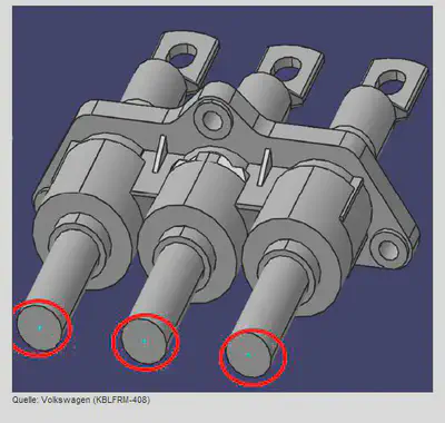
The picture above shows an example of connector with multiple segment connection points (sometimes also called bundle postion / connection points). The segment connection points are marked with red circles. Such connectors have multiple entry points for wires, that can be used alternatively or at the simultaniously. The geometric position of the segment connection points is different, that they have to be treated individually, so each segment connection point is accessed via an individual SegmentConnectionPoint
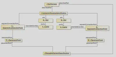
The example shows a connector that has two cavity, that are only reachable through different segment connection points. By associating these SegmentConnectionPoints with corresponding PlacementPoints the SegmentConnectionPoint become ‘placeable’ on nodes in the topology of a harness.
Wire Addons
Cavities
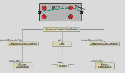
This example shows how add-ons for cavities in a connector could be defined. In this example, the ConnectorHousingSpecification has two different SegmentConnectionPoints. Each of them is defining it’s own CavityAddOn. So depending on the SegmentConnectionPoint used, a Cavity can have for example 50mm as well as 150mm as Add-On.
Modular Slots
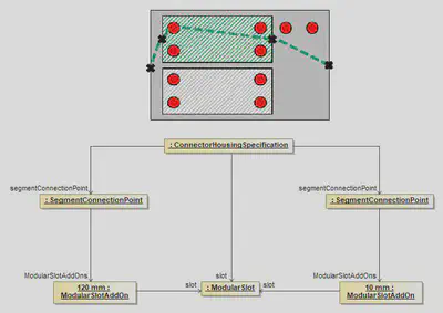
If a ConnectorHousingSpecification has ModularSlots, the Add-ons are not defined individually for all cavities for all possible inserts, but only per ModularSlot. The Add-On defined in the ModularSlotAddOn, is the Add-On need to reach the ModularSlot from the corresponding SegmentConnectionPoint. The add-on needed to reach a certain cavity in an used insert, can be obtain from ConnectorHousingSpecification of the used insert.
ConnectorHousingCap
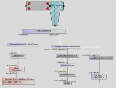
Wire add-ons caused by cap’s are defined in the ConnectorHousingCapSpecification. The specified value is the add-on required to reach the SegmentConnectionPoint of the ConnectorHousing from the entry point of the cap.