Splices
Change History
| Id | Subject | Date |
| Latest Commit | Complete rework of wire protections after clarification of Node- & SegmentLocations (#935) | 2026-01-28 |
| KBLFRM-855 | Splice: Number of wires from the left / number of wires from the right | 2022-10-21 |
Before reading this implementation guideline, it is highly recommended to read the following sections in the VEC Online Model Description first:

A splice is normally used to create a contacting between multiple wires with the same potential e.g. for ground distribution. A splice can be created with or without real material (e.g. ultra-sonic welding vs. crimping). The figure above is a schematic illustration of the two common types of splices. On the left side is an end splice, on the right side an inline or parallel splice. The following sections will give you a comparison of those variants every time a different handling is needed. To do so the examples of an end splice with just two wire ends and an inline splice with one wire end on the left and two wire ends on the right will be used. (see figure 2 + 3)
Part Master Definition
Technical Properties
In the VEC the technical properties of splices are defined with a SpliceTerminalSpecification. The specification can represent a process definition (e.g. for ultra-sonic welding) or a real component (e.g. the sleeve for crimped splices).
The different types of splices are defined with the inner structure of the specification (WireReceptions and their relations)
 |  |
|---|---|
 WireReception is needed |  SpliceTerminalSpecification contains a wire reception for each side. |

InternalTerminalConnection, the default assumption is that all recepetions (wire & terminal) are short circuited (have the same potential). So, for most regular splices it is not required to defined InternalTerminalConnections.Placeability
To allow the placement of a splice in the topology it requires a PlaceableElementSpecification (compare Placement and Dimensions).
| In case of an inline splice it might be neccessary to know / to specify the orientation of the splice in the topology. The details of a placement are defined with individual PlacementPoints in the PlaceableElementSpecification.To associate this with the splice specific properties, a WireReception can reference the PlacementPoint that represents itself in the placement. |
Usage
Instantiation
Instances are required when using splices in a harness or wiring definition (see Instances of Components). Splice specific properties are defined with a SpliceTerminalRole. The role contains all instance information about the splice like sealing or insulation and it also contains a WireReceptionReference foreach WireReception in the part master definition.
| |
|---|---|
The end splice needs just one WireReceptionReference | In case of the inline splice two WireReceptionReferences have to be put in the SpliceTerminalRole |
To define reference elements for definition of the placement of a splice in the topolgy, a PlaceableElementRole has to be put inside the instance representation. This is valid for both example cases.
| When the direction of the inline splice shall be specified, it is necessary to create PlacementPointReferences underneath the PlaceableElementRole. They represent the spots of the splice which shall be placed in the topology instead of the whole splice itself. For the inline splice example two PlacementPointReferences are required, referencing the PlacementPoints from the master data definition. |
Contacting
Splices exist in 100% or 150% configurations (e.g. to create a ground distribution point for wires from different modules). The part master definition of the splice contains exactly one WireReception if it is an End-Splice. In case of an Inline (e.g. a Parallel Splice) the part master data definition contains as many Wirereceptions as directions exists from which a contacting can be realized.
Different predefined contacting variants (100%) of the splice are expressed by one ContactPoint per variant. If the splice has no variants, it defines just one ContactPoint. If the splice is undefined at design time and actual variants are only known at manufacturing time, one ContactPoint per WireEnd shall be used.
If different configurations require different terminal / contacting material (e.g. crimp sleeves) the corresponding material needs to be expressed by a new splice instance (part master data + instance + contact points for all variants with new material). This is the same situation when a certain position can be realized with connector housing with different number of cavities. If different configurations require (different) additional material (e.g. sealings) it is also referenced from the ContactPoints as WireEndAccessory.
For inline splices (more than one WireReception) there are situations where the allocation of wires to sides / wire receptions is free or is not explicitly defined. However, if it necessary to defines this assignment explicitly WireMountingDetails are added to the WireMounting in the ContactPoint. The WireMountingDetail defines which WireEnds are related to which WireReceptionReference.
Placement
The splice terminal is placed in the topology with a Placement contained in a PlacementSpecification and a PlaceableElementRole contained in the OccurrenceOrUsage. A detailed description can be found in the specification “Placement and Dimensions” and corresponding implementation guideline.
If a splice has more than one WireReception and if it is required to define the exact orientation of the splice in the topology, or the splice has such a size that the exact positioning makes a geometrical difference (e.g. high voltage splices), then such a definition is possible in the VEC.
A prerequisite for this is, that the topology has to define individual TopologyNodes for each WireReceptionReference, instead of one node, when orientation is irrelevant (see figure below).

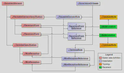
The details of the placement are then defined with references between the corresponding NodeLocations and the PlacementPointReferences representing the WireReceptionReferences (compare the instance diagram below).
WireReceptionReferences, PlacementPointReferences etc. can be omitted.XML-Example
The following XML listings show an example of splice instance with placed WireReceptions
Part Master Data
<DocumentVersion id="documentVersion_1">
        [...]
        <ReferencedPart>partVersion_1</ReferencedPart>
        <Specification id="wireReceptionSpecification_1" xsi:type="vec:WireReceptionSpecification" >
            <Identification>SpliceReception</Identification>
            <CoreCrossSectionArea id="valueRange_1">
                <Minimum>0.5</Minimum>
                <Maximum>1.5</Maximum>
                [...]
            </CoreCrossSectionArea>
        [...]
        </Specification>
        <Specification id="spliceTerminalSpecification_1" xsi:type="vec:SpliceTerminalSpecification">
            <Identification>Splice</Identification>
            <DescribedPart>partVersion_1</DescribedPart>
            <WireReception id="wireReception_1">
                <Identification>Left</Identification>
                <WireReceptionSpecification>wireReceptionSpecification_1</WireReceptionSpecification>
                <PlacementPoint>placementPoint_1</PlacementPoint>
            </WireReception>
            <WireReception id="wireReception_2">
                <Identification>Right</Identification>
                <WireReceptionSpecification>wireReceptionSpecification_1</WireReceptionSpecification>
                <PlacementPoint>placementPoint_2</PlacementPoint>
            </WireReception>
        </Specification>
        <Specification id="placeableElementSpecification_1" xsi:type="vec:PlaceableElementSpecification">
            <Identification>Pes</Identification>
            <PlacementPoint id="placementPoint_1">
                <Identification>First</Identification>
            </PlacementPoint>
            <PlacementPoint id="placementPoint_2">
                <Identification>Second</Identification>
            </PlacementPoint>
        </Specification>
        [...]
    </DocumentVersion>

     <PartVersion id="partVersion_1">
        <CompanyName>The VEC Company Ltd.</CompanyName>
        <PartNumber>007_123</PartNumber>
        <PartVersion>1</PartVersion>
        <PrimaryPartType>SpliceTerminal</PrimaryPartType>
    </PartVersion>
Instance
<PartOccurrence id="partOccurrence_1">
        <Role xsi:type="vec:PlaceableElementRole" id="placeableElementRole_1">
             <Identification>PlaceableElementRole</Identification>
             <PlaceableElementSpecification>placeableElementSpecification_1</PlaceableElementSpecification>
             <PlacementPointReference id="placementPointReference_1">
                 <Identification>placementPointReference_1</Identification>
                 <PlacementPoint>placementPoint_1</PlacementPoint>
             </PlacementPointReference>
             <PlacementPointReference id="placementPointReference_2">
                 <Identification>placementPointReference_2</Identification>
                 <PlacementPoint>placementPoint_2</PlacementPoint>
             </PlacementPointReference>
         </Role>
        <Role xsi:type="vec:SpliceTerminalRole" id="spliceTerminalRole_1">
            <Identification>SpliceTerminalRole</Identification>
            <TerminalSpecification>spliceTerminalSpecification_1</TerminalSpecification>
            <WireReceptionReference id="wireReceptionReference_1">
                <Identification>Left</Identification>
                <WireReception>wireReception_1</WireReception>
            </WireReceptionReference>
            <WireReceptionReference id="wireReceptionReference_2">
                <Identification>Right</Identification>
                <WireReception>wireReception_2</WireReception>
            </WireReceptionReference>
        </Role>
        <Part>partVersion_1</Part>
    </PartOccurrence>
Placement
  <Specification xsi:type="vec:PlacementSpecification" id="placementSpecification_1">
        <Identification>PLACEMENT</Identification>
        <Placement xsi:type="vec:OnPointPlacement" id="placement_1">
            <Identification>Splice</Identification>
            <Location xsi:type="vec:NodeLocation" id="location_1">
                <Identification>Left</Identification>
                <ReferencedNode>node_1</ReferencedNode>
                <PlacedPlacementPoints>placementPointReference_1</PlacedPlacementPoints>
            </Location>
            <Location xsi:type="vec:NodeLocation" id="location_2">
                <Identification>Rigth</Identification>
                <ReferencedNode>node_2</ReferencedNode>
                <PlacedPlacementPoints>placementPointReference_2</PlacedPlacementPoints>
            </Location>
        </Placement>
        [...]
    </Specification>
    <Specification xsi:type="vec:TopologySpecification" id="topologySpecification_1">
        <TopologyNode id="node_1">
            <Identification>PNID1</Identification>
        </TopologyNode>
        <TopologyNode id="node_2">
            <Identification>PNID2</Identification>
        </TopologyNode>
    </Specification>