Wires
Change History
| Id | Subject | Date |
| Latest Commit | Removed review annotations. | 2025-12-08 |
| #1143 | Adapted to structural changes / deprecations of WireElement / WireElementSpecificaiton relations in VEC version 2.2.0 | 2025-11-04 |
| KBLFRM-1234 | Added description for layering and odering of wire elements. | 2024-12-19 |
| KBLFRM-1214 | Added a section about wire length, wire ends, stripping and cutting. | 2023-11-06 |
| KBLFRM-953 | Complete restructuring of the guideline according to comments in the review of KBLFRM-953. Clarification of the guideline for layering of wire elements in multicore. Integration of additional samples. | 2021-04-14 |
| KBLFRM-1032 | Added an XML example for the structure of a complex wire | 2021-03-17 |
| KBLFRM-953 | Adapted to structural changes of wires in VEC version 1.2.0 | 2020-10-29 |
This Implementation Guideline covers the various aspects of a correct wire representation in the VEC for different scenarios and variants of wires. It covers both multi cores and single cores.
The VEC contains model elements for the representation of wires which would not be strictly necessary for the exclusive representation of single core wires. However, single core wire elements with the same specification can occur in both, single and multi-core wires. In order to achieve a consistent representation of all cases in the model and in order to allow the reuse of data elements, a uniform modelling approach was chosen for single and multicore wires. At the first glance, this may seem unnecessarily complicated in the case of single core wires, but it simplifies the mapping of wires in the VEC on the long run, when all kinds of wires and not only single-cores have to be supported.
Specifying the Elements of a Wire
In the world of the VEC, a wire is a hierarchical structure of WireElements. A wire element can be any node in the hierarchy that has to be addressed individually for the definition of specific properties. A wire element can be manifested either by physical material (e.g. a core, an insulation, a shield) or by the logical necessity for the definition of certain product properties during the production process (e.g. a grouping for twisted pairs).
The properties of WireElement are defined with a WireElementSpecification (see the figure below).

The WireElementSpecification is a generic, reusable definition of the properties of a wire element. That means, multiple WireElements can reference the same WireElementSpecification, if they share the same technical properties. A specified wire element can be used in different contexts. For example, a white single core can be used as individual single core wire or as part of several different multi core wires. It can even be used multiple times as part of the same multi core (compare CAT7 twisted pair cables that might contain up to 4 similar white cores). Therefore, the definition is represented by a WireElementSpecification, which is independent of a specific WireSpecification.
The actual technical properties of a wire element are defined by referencing a corresponding auxiliary specifications. For example (see the Diagram Wire in the recommendation for a complete list):
InsulationSpecificationif the wire element has insulation properties, and/orConductorSpecificationif the wire element has conducting properties.
WireElementSpecification was also used to define the hierarchical structure of a wire. However, this approach turned out to insufficient for an unambiguous representation of complex wires (see next section for details). Therefore, since VEC version 2.2.0 the hierarchical structure of a wire is defined by the WireElements only and the use of WireElementSpecification.SubWireElementSpecification is discouraged.WireElementSpecification. For example, in the real world all FLRY wires with a specific cross section area have the same properties for the core. This can (not a must) be expressed in the VEC by sharing the same CoreSpecification.From the individual Elements to a whole Wire
From a part master data perspective, the WireElementSpecification was (pre VEC V2.2) sufficient to describe a wire with all its aspects, when navigating from the root wire element to its leaves. However, the ability to reuse WireElementSpecifications within a {{ vec-class WireSpecification }} or between multiple wires introduced a draw back:
Referencing a
WireElementSpecificationdoes not unambiguously define which wire element is actually meant in the context of its usage.
The following figure shall illustrate this. The red lines are hypothetical associations for the demonstration of the problem. In the VEC those associations do not exist, because of the described problem the actual model is different.
When navigating from a part master data perspective (e.g. PartVersion A → Composite-Wire B → White-Core) the context is unambiguously defined by the navigation path. However, in the model the part master data is normally used somewhere, for example the wire is used somewhere in the harness. This is indicated by the RoutedWire in the figure. In that case, it is vital to know which wire element in which wire is actually meant. However, when doing a reverse navigation in the model, indicated by the red lines, it is not clear which white core is actually meant. The white core is reused in multiple wires (or in multiple locations within the same wire). Therefore, the context is ambiguous.

To solve this dilemma, the VEC introduced the WireSpecification and the WireElement. The WireSpecification is the PartOrUsageRelatedSpecification of a wire and the mandatory root of any wire (element) that can be used as an individual component. It references the root WireElement and the root WireElementSpecification (deprecated since VEC V2.2).
The WireElement is the context specific handle of a WireElementSpecification in a specific WireSpecification (primarily needed for multi cores, but due to a consistent modelling approach also mandatory for single cores). The WireElement also defines the actual hierarchy of the wire elements within the wire. The WireElements are used as a target for references.
WireElementSpecification and WireElements has been deprecated with VEC V2.2, because for a precise definition of the hierarchy the WireElementSpecification.SubWireElementSpecification was insufficient and incomplete, especially when using the same specification multiple times. Therefore, this association was deprecated and the reuse of complex structures among multiple wires is not supported anymore. However, the hierarchical structure of a wire is now unambiguously defined by the WireElements only.Definition of a Single Core

The figure above illustrates the representation of a single core wire in the VEC. The WireSpecification is the PartOrUsageRelatedSpecification describing a PartVersion. Each WireSpecification has a single root WireElement that serves as the context specific handle of the WireElementSpecification (see above).
In theory, there are two possible representations for single cores in the VEC (see the figure below). A minimal representation, where the single core is represented by one wire element with conducting and insulating properties at the same time, and a more extensive one, where the single core is represented by two hierarchical wire elements, one for the insulation and one for the actual core.
WireElementSpecification shall always be used. Otherwise the number of objects and structures in the model are inflated without additional information or benefits.
XML Listing
The following is a XML listing of the VEC representation of the single core (complete file can be downloaded at the end of the page). To illustrate the purpose of the different specifications more clearly, the listing also contains some additional technical properties, that are not contained in the figures above.
<?xml version="1.0" ?>
<vec:VecContent xmlns:xsi="http://www.w3.org/2001/XMLSchema-instance" xmlns:vec="http://www.prostep.org/ecad-if/2011/vec" id="Content_00000" xsi:schemaLocation="">
  <VecVersion>2.2.0</VecVersion>
  <GeneratingSystemName>VEC Samples</GeneratingSystemName>
  <DateOfCreation>2025-11-04T12:52:59.048113500Z</DateOfCreation>
  <GeneratingSystemVersion>0.0.1</GeneratingSystemVersion>
  <DocumentVersion id="DocumentVersion_00001">
    <CompanyName>Acme Inc.</CompanyName>
    <DocumentNumber>DRAW-WIRE</DocumentNumber>
    <DocumentType>PartMaster</DocumentType>
    <DocumentVersion>1</DocumentVersion>
    <ReferencedPart>PartVersion_00017</ReferencedPart>
    <Specification xsi:type="vec:GeneralTechnicalPartSpecification" id="GeneralTechnicalPartSpecification_00002">
      <Identification>GTPS-WIRE</Identification>
      <DescribedPart>PartVersion_00017</DescribedPart>
      <MassInformation id="MassInformation_00003">
        <DeterminationType>Measured</DeterminationType>
        <Value id="NumericalValue_00004">
          <UnitComponent>CompositeUnit_00020</UnitComponent>
          <ValueComponent>4.6</ValueComponent>
        </Value>
        <ValueSource>Series</ValueSource>
      </MassInformation>
    </Specification>
    <Specification xsi:type="vec:CoreSpecification" id="CoreSpecification_00005">
      <Identification>Core-WIRE</Identification>
      <CrossSectionArea id="NumericalValue_00006">
        <UnitComponent>SIUnit_00021</UnitComponent>
        <ValueComponent>0.35</ValueComponent>
      </CrossSectionArea>
      <NumberOfStrands id="NumericalValue_00007">
        <UnitComponent>OtherUnit_00023</UnitComponent>
        <ValueComponent>7.0</ValueComponent>
      </NumberOfStrands>
      <StrandDiameter id="NumericalValue_00008">
        <UnitComponent>SIUnit_00022</UnitComponent>
        <ValueComponent>0.27</ValueComponent>
      </StrandDiameter>
    </Specification>
    <Specification xsi:type="vec:InsulationSpecification" id="InsulationSpecification_00009">
      <Identification>Ins-WIRE</Identification>
      <Thickness id="NumericalValue_00010">
        <UnitComponent>SIUnit_00022</UnitComponent>
        <ValueComponent>0.2</ValueComponent>
      </Thickness>
    </Specification>
    <Specification xsi:type="vec:WireElementSpecification" id="WireElementSpecification_00011">
      <Identification>1</Identification>
      <Type id="WireType_00012">
        <Type>FLRY-A</Type>
        <ReferenceSystem>DIN 76722</ReferenceSystem>
      </Type>
      <OutsideDiameter id="NumericalValue_00013">
        <UnitComponent>SIUnit_00022</UnitComponent>
        <ValueComponent>1.3</ValueComponent>
        <Tolerance id="Tolerance_00014">
          <LowerBoundary>-0.1</LowerBoundary>
          <UpperBoundary>0.0</UpperBoundary>
        </Tolerance>
      </OutsideDiameter>
      <ConductorSpecification>CoreSpecification_00005</ConductorSpecification>
      <InsulationSpecification>InsulationSpecification_00009</InsulationSpecification>
    </Specification>
    <Specification xsi:type="vec:WireSpecification" id="WireSpecification_00015">
      <Identification>WS-WIRE</Identification>
      <DescribedPart>PartVersion_00017</DescribedPart>
      <WireElementSpecification>WireElementSpecification_00011</WireElementSpecification>
      <WireElement id="WireElement_00016">
        <Identification>1</Identification>
        <WireElementSpecification>WireElementSpecification_00011</WireElementSpecification>
      </WireElement>
    </Specification>
  </DocumentVersion>
  <PartVersion id="PartVersion_00017">
    <CompanyName>Acme Inc.</CompanyName>
    <PartNumber>WIRE</PartNumber>
    <PartVersion>1</PartVersion>
    <PrimaryPartType>Wire</PrimaryPartType>
  </PartVersion>
  <Unit xsi:type="vec:SIUnit" id="SIUnit_00018">
    <Exponent>-1</Exponent>
    <SiUnitName>Metre</SiUnitName>
  </Unit>
  <Unit xsi:type="vec:SIUnit" id="SIUnit_00019">
    <SiUnitName>Gram</SiUnitName>
  </Unit>
  <Unit xsi:type="vec:CompositeUnit" id="CompositeUnit_00020">
    <Factors>SIUnit_00019 SIUnit_00018</Factors>
  </Unit>
  <Unit xsi:type="vec:SIUnit" id="SIUnit_00021">
    <Exponent>2</Exponent>
    <SiUnitName>Metre</SiUnitName>
    <SiPrefix>Milli</SiPrefix>
  </Unit>
  <Unit xsi:type="vec:SIUnit" id="SIUnit_00022">
    <SiUnitName>Metre</SiUnitName>
    <SiPrefix>Milli</SiPrefix>
  </Unit>
  <Unit xsi:type="vec:OtherUnit" id="OtherUnit_00023">
    <OtherUnitName>Piece</OtherUnitName>
  </Unit>
</vec:VecContent>
Definition of a Multicore Wire

The figure on the right illustrates a “simple” multicore wire, that will serve as an example for the following sections. It consists of two single cores of different colouring that form a twisted pair: “A”, a green one and “B” a blue one. Around the twisted pair is a shielding (braiding or foil) and an outer insulation (sheath).
The figure below displays the structural representation of the example in the terms of the VEC. On the left side is the WireSpecification with its contained WireElements. To emphasis the hierarchical containment of the WireElements, which can also be found in the XML structure, they are represented with nested boxes. On the right side are the WireElementSpecification. Corresponding WireElements and WireElementSpecifications are highlighted in the same colours. The technical properties of the WireElementSpecification are defined in the referenced auxiliary specifications.

Notable things in this example:
- The specification of the smallest elements of the multicore, the single cores (one outlined in red), is similar to the specification of an individual single core. It could even be the same
WireElementSpecification. - Since the only difference between Core “A” & “B” is the different insulation colouring, they share the same
CoreSpecification. - The different layers around the two cores (twisting, shielding, insulation) are represented by individual
WireElement/WireElementSpecification. This is in contrast to the single core where insulation and conductor are represented by a singleWireElement/WireElementSpecification.
WireSpecification → WireElementSpecification → WireElementSpecification is redundant to WireSpecification → WireElement → WireElement and has been deprecated since VEC version 2.2.0.
Open Electrical, CC BY-SA 3.0 https://creativecommons.org/licenses/by-sa/3.0, via Wikimedia Commons
The last point requires a somewhat more detailed explanation. Why does the multicore representation differ in this aspect from the single core representation?
As discussed earlier: for single cores a minimized representation shall be used, because otherwise the model gets unnecessarily bloated. However, multicores can be inherently complex (see “Cutaway Diagram…” on the left). Using a minimized representation in multicores for others than the smallest elements ( the single cores) would create wide open space for ambiguous interpretations.
For example, having a WireElementSpecification with a ShieldSpecification and an InsulationSpecification: What is the order of layering? Which one comes first? Another example, a foil shield in combination with a braiding and an insulation. A WireElementSpecification could only carry one ConductorSpecification, so one of the two shieldings get individual wire element, whereas the other one is combined with the insulation. Isn’t that inconsistent? And these are just two problematic cases and many more are conceivable. To avoid this confusion, the following applies for multicores:
WireElementSpecifications of higher levels (not single cores used in a multicore) shall only represent one Character / Element / Property in the multicore. WireElementSpecification that have a grouping, conducting, insulating or similar character at the same time are not permitted.Another reason for not using a minimized representations for higher level multicore wire elements is, that most manufacturing processes require the individual identification of the different elements (e.g. shield an insulation) and those are often processed in different manufacturing steps.
XML Listing
The following is a XML listing of the VEC representation of the multicore example illustration. The listing is a schema valid VEC. However, for the sake of the simplicity of the example it just contains the most fundamental properties. The Identification values for the Specifications are chosen in a way to make the example more readable. In a productive VEC the Identification-values would be defined in an appropriate way for the creating process.
<?xml version="1.0" encoding="UTF-8"?>
<vec:VecContent xmlns:vec="http://www.prostep.org/ecad-if/2011/vec"
    xmlns:xsi="http://www.w3.org/2001/XMLSchema-instance" id="id_0001">
    <VecVersion>1.2.0</VecVersion>
    <DocumentVersion id="id_1">
        <CompanyName>ACME Inc.</CompanyName>
        <DocumentNumber>0815</DocumentNumber>
        <DocumentType>PartMaster</DocumentType>
        <DocumentVersion>a</DocumentVersion>
        <!-- Auxiliary specifications for the multicore -->
        <Specification id="id_1_1" xsi:type="vec:InsulationSpecification">
            <Identification>Orange</Identification>
            <BaseColor id="id_1_1_0001">
                <Key>#FF8000</Key>
                <ReferenceSystem>RGB</ReferenceSystem>
            </BaseColor>
        </Specification>
        <Specification id="id_1_2" xsi:type="vec:ShieldSpecification">
            <Identification>Shielding</Identification>
            <CrossSectionArea id="id_1_2_0001">
                <UnitComponent>id_unit_mm2</UnitComponent>
                <ValueComponent>1.5</ValueComponent>
            </CrossSectionArea>
        </Specification>
        <Specification id="id_1_3" xsi:type="vec:WireGroupSpecification">
            <Identification>Twisting</Identification>
            <GroupType>Twisted</GroupType>
            <LengthOfTwist id="id_1_3_0001">
                <UnitComponent>id_unit_mm</UnitComponent>
                <ValueComponent>40</ValueComponent>
            </LengthOfTwist>
        </Specification>
        <!-- Auxiliary specifications for the two single cores -->
        <Specification id="id_2_1" xsi:type="vec:CoreSpecification">
            <Identification>Core</Identification>
            <CrossSectionArea id="id_2_1_0001">
                <UnitComponent>id_unit_mm2</UnitComponent>
                <ValueComponent>0.35</ValueComponent>
            </CrossSectionArea>
        </Specification>
        <Specification id="id_2_2" xsi:type="vec:InsulationSpecification">
            <Identification>Green</Identification>
            <BaseColor id="id_2_2_0001">
                <Key>#00CC00</Key>
                <ReferenceSystem>RGB</ReferenceSystem>
            </BaseColor>
        </Specification>
        <Specification id="id_3_2" xsi:type="vec:InsulationSpecification">
            <Identification>Blue</Identification>
            <BaseColor id="id_3_2_0001">
                <Key>#0050EF</Key>
                <ReferenceSystem>RGB</ReferenceSystem>
            </BaseColor>
        </Specification>
        <!-- Buttom Up definition of the WireElementSpecification (from single cores to Multicore) -->
        <Specification id="id_4_1" xsi:type="vec:WireElementSpecification">
            <Identification>A</Identification>
            <ConductorSpecification>id_2_1</ConductorSpecification>
            <InsulationSpecification>id_2_2</InsulationSpecification>
        </Specification>
        <Specification id="id_4_2" xsi:type="vec:WireElementSpecification">
            <Identification>B</Identification>
            <ConductorSpecification>id_2_1</ConductorSpecification>
            <InsulationSpecification>id_3_2</InsulationSpecification>
        </Specification>
        <Specification id="id_4_3" xsi:type="vec:WireElementSpecification">
            <Identification>Twisted-Pair</Identification>
            <SubWireElementSpecification>id_4_1 id_4_2</SubWireElementSpecification>
            <WireGroupSpecification>id_1_3</WireGroupSpecification>
        </Specification>
        <Specification id="id_4_4" xsi:type="vec:WireElementSpecification">
            <Identification>Shield</Identification>
            <ConductorSpecification>id_1_2</ConductorSpecification>
            <SubWireElementSpecification>id_4_3</SubWireElementSpecification>
        </Specification>
        <Specification id="id_4_5" xsi:type="vec:WireElementSpecification">
            <Identification>Insulation</Identification>
            <InsulationSpecification>id_1_1</InsulationSpecification>
            <SubWireElementSpecification>id_4_4</SubWireElementSpecification>
        </Specification>
        <!-- WireSpecification with WireElemnts -->
        <Specification id="id_5_0" xsi:type="vec:WireSpecification">
            <Identification>Multi-Core WireSpecification</Identification>
            <DescribedPart>id_2</DescribedPart>
            <WireElementSpecification>id_4_5</WireElementSpecification>
            <WireElement id="id_5_1">
                <Identification>Root</Identification>
                <WireElementSpecification>id_4_5</WireElementSpecification>
                <SubWireElement id="id_5_2">
                    <Identification>Insulation</Identification>
                    <WireElementSpecification>id_4_5</WireElementSpecification>
                    <SubWireElement id="id_5_3">
                        <Identification>Shield</Identification>
                        <WireElementSpecification>id_4_4</WireElementSpecification>
                        <SubWireElement id="id_5_4">
                            <Identification>Twisted-Pair</Identification>
                            <WireElementSpecification>id_4_3</WireElementSpecification>
                            <SubWireElement id="id_5_5">
                                <Identification>A</Identification>
                                <WireElementSpecification>id_4_1</WireElementSpecification>
                            </SubWireElement>
                            <SubWireElement id="id_5_6">
                                <Identification>B</Identification>
                                <WireElementSpecification>id_4_2</WireElementSpecification>
                            </SubWireElement>
                        </SubWireElement>
                    </SubWireElement>
                </SubWireElement>
            </WireElement>
        </Specification>
    </DocumentVersion>
    <PartVersion id="id_2">
        <CompanyName>ACME Inc.</CompanyName>
        <PartNumber>4711</PartNumber>
        <PartVersion>a</PartVersion>
        <PrimaryPartType>Wire</PrimaryPartType>
    </PartVersion>
    <Unit id="id_unit_mm2" xsi:type="vec:SIUnit">
        <Exponent>2</Exponent>
        <SiUnitName>Metre</SiUnitName>
        <SiPrefix>Milli</SiPrefix>
    </Unit>
    <Unit id="id_unit_mm" xsi:type="vec:SIUnit">
        <SiUnitName>Metre</SiUnitName>
        <SiPrefix>Milli</SiPrefix>
    </Unit>
</vec:VecContent>
Ordering & Layering of WireElements

When specifying complex wires, the order and layering of WireElements must be specifiable in some case. An example of this can be seen on the right in Figure “Complex Wire Structure”.
The hierarchical subWireElement relationship between WireElements is defined with a “contained in” semantics and is strictly hierarchical. In this sense, all conductors A-F in the example are sub-elements of the root element, the cable sheath. Although conductor F is located within the circle formed by A-E, it is not a true sub-element of any of the other elements. This merely represents the spatial arrangement of the elements relative to one another at the same level of hierarchical definition. This arrangement is defined with attributes layer and index within the WireElement.
The layer defines levels for the SubWireElements of an individual WireElement from the inside to the outside. WireElement with same value for level are on the same level. The index defines a natural order on the WireElements that are on the same level. Meaning, two WireElements A & B are next to each other when there is no WireElement C with C.index value between A.index and B.index. The index defines an order, not a direction (e.g. clockwise vs. counter clockwise), since that dependends on the viewing direction (see figure).
If any SubWireElement of a WireElement defines layer or index, all SubWireElement of this WireElement shall define it.
The following diagram shows the corresponding structure with WireElements. The WireElementSpecifications were omitted for the sake of clarity.

Ribbon cables are also an example where the index is relevant.
layer and index within the WireElement results in this information being part of the WireSpecification rather than the WireElementSpecification. Consequently, this means that this information cannot be shared between different WireSpecifications. This was an intentional design decision, as the use case for such information reuse is very limited on one hand, while on the other hand, the complexity of the modeling required for such a reuse would have increased drastically.Special Cases of Wires
Ribbon Cables

Heron 21:16, 22 Nov 2004 (UTC), CC BY-SA 3.0 http://creativecommons.org/licenses/by-sa/3.0/, via Wikimedia Commons
The figure on the left shows two variants of ribbon cables. As can be easily seen, in such a cable the same cores are present several times on the same level of the hierarchy. This is one of the cases referred to in “From the individual Elements to a whole Wire” that require the definition of individual WireElements where the WireElementSpecification alone would not be sufficient.
The figure below displays the structural representation of the example in terms of the VEC.

The illustration represents a five-core ribbon cable. On the left is the WireSpecification with its contained WireElement, on the right side the WireElementSpecifications. The ribbon cable consists of one red core and 4 identical grey cores. Therefore there are only two WireElementSpecifications for the cores, one for the red core and one for all grey cores. To define explicitly that the ribbon cable consists of 5 cores, the Root-WireElementSpecification references the single Grey-Core four times as subWireElementSpecification.
In the WireSpecification there are individual WireElements for each core (Core: 1, 2, 3, 4, 5). Since the VEC does not define the geometric arrangement of subWireElements within a WireElement the four grey cores have to be identified with their respective identification (e.g. 2 - 5).
CAT7 - S/FTP

Original: Uwe Schwöbel (de:Datei:SSTP-Kabel.png)English translation: Deelkar (en:File:S-STP-cable.png)Vector conversion: Svgalbertian, GFDL http://www.gnu.org/copyleft/fdl.html, via Wikimedia Commons
Ru wiki, Public domain, via Wikimedia Commons
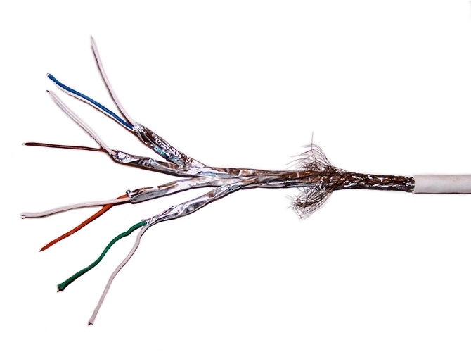
The figures on the right side illustrate cases of more complex mulitcore wires. For example Category 7 Ethernet cables according to ISO/IEC 11801 2nd Ed. (2002). These consist of a multilayer structure of conductors with insulation, twisting and different shielding.
Remarkable is that each pair of cores consists of a primary coloured core and a primary/white coloured core (e.g. blue and blue/white). However, in reality the primary colour on the primary/white core is often omitted, as it is unambiguously identifiable due to its twisting & shielding together with the primary coloured core in the cable. So the blue/white core is often actually just a plain white core. Therefore, such a multicore cable can consist of four primary coloured cores and 4 identical white coloured cores.
The figure below displays the structural representation of the example in terms of the VEC. In order to achieve a rudimentary clear representation, the auxiliary specifications for the WireElementSpecification have been omitted. For the same reason, the twisted-pairs 3 & 4 have omitted as well.

Again, on the left side is the WireSpecification with its contained WireElement, on the right side the WireElementSpecifications. It is worth noting that the white cores are represented by a single WireElementSpecification, whereas each is represented by an individual WireElements.
WireLength, WireEnds and Cutting & Stripping (especially for multi cores)
WireEnd, required to create a detailed definition of the different lengths at the end of a wire and the displacement of the WireElements to each other, were first introduced with version 2.1.The VEC always allowed the definition of specific WireLength values for the individual WireElementReferences of a wire. However, this does not define how the WireElementReferences relate to each other, i.e. what the displacement of each is, since the cutting and stripping of a multi-core does not necessarily has to be symmetric. With VEC 2.1 concepts for this have been introduced and this section of this implementation guideline gives a detailed explanation of their usage. The complete section is based on the figure “WireLength, WireEnds and Cutting & Stripping” below.

On the right hand side of the figure is a sectional view of the multi-core that should serve as an example throughout this explanation. There are also names (SHIELD, INSULATION, CORE1, …) defined for the WireElementReferences which will be used in the following to reference those elements in the figure. On the left hand side are two illustrations of longitudinal cuts through the same multi-core. The upper one shows the multi-core after it has been cut to its length “overall length”, the lower one is after cutting and stripping of the individual wire elements. See the “S/FTP CAT7” picture in the previous section for a “real world” example.
The DMU length (upper illustration WireLength[type=“y”]) is often calculated from the sum of all length values of all TopologySegments through which the wire is routed. This is the length between the SegmentConnectionPoints of the corresponding connectors. During production (upper illustration WireLength[type=“x”]), additional length is required (e.g. in the connectors indicated as ΔA & ΔB or for other length discrepancies like the position in a curved segment, not illustrated in the picture). However, the VEC is not keeping track of the individual contributions of the different factors to the overall Δ (there is no definition of ΔA or ΔB in the VEC).
In the case of a multi core, each WireElementReference can have an individual length (see INSULATION.WireLength, SHIELD.WireLength, CORE1.WireLength,… in the lower left area of the figure). This information alone lacks a definition of the displacement of the WireElementReferences to each other. This is sufficient for some use cases (e.g. weight calculation), but it can not serve as a “product definition” for the stripped multi-core. To fully define the situation illustrated above, the attributes of the WireEnd, especially CutBackLength & StrippingLength, are required.
The PositionOnWire-Attributes in the WireEnds define an order on the WireEnds of a WireElementReference. The values “0.0” and “1.0” are reserved for the two genuine ends of the wire. The values between are used for WireEnds between them (e.g. Insulation Displacement Connectors abbr. IDC). These are not considered in detail in this example, as they are rather unlikely in the case of such a multicore.
The following definitions apply to the WireEnd (see class documentation):
- For a multi-core it is defined, that all
WireEnds with the same PositionOnWire are on the same side of the multi-core (in the illustration 0.0 on the left side and 1.0 on the right side). - The CutBackLength of a
WireEndis defined relative to the outermostWireElementReferenceof theWireRole(INSULATION in our case). - The StrippingLength is defined relative to the
WireEnd, whose position is defined by the CutBackLength (see previous bullet point).
The consequences of this can be seen in the illustration. The reference for the definition on the left and right hand side is the overall length of the wire. On the right side the CORE3 (yellow) is cut back by the length “a” and then stripped from its insulation with the length “b”. On the left side, the same core is not cut back at all, but stripped with the length c. Since CORE3 is a “single-core wire element” (no sub-wire elements, see definition above) it defines per WireEnd a CutBackLength (cutting of the core & the insulation) and a StrippingLength (stripping the insulation from the remaining core).
The SHIELD on the left hand side only defines a CutBackLength=“d” since it is a wire element without insulation (see how to represent a multi-core in the previous sections). Consequently the INSULATION does not define a CutBackLength, as there is no conductor to cut and the sub wire elements carry their own definitions. The length “e” is the StrippingLength of the INSULATION.
Remarks:
- This definition of the cutting & stripping is independent from any specific wire length type.
- This is a definition of the final result of a “cut & strip” process, it does not imply any order or steps how to achieve this result.