ECUs, EE-Components and Component Boxes
E/E components, represented in the VEC by the EEComponentSpecification and
EEComponentRole, summarize all kinds of components with a more or less
complex electrical function. In the VEC the description of an E/E component is a combination of
the following (optional) aspects:
- Connector Interface / EE Component Header: Defines the properties and possibilities for a connection to a wiring harness or other e/e components.
- Internal Connectivity: Defines the electrical connectivity within a e/e component.
- Switching States: Add variability of a certain degree to the internal connectivity.
- Electrical Interface: Defines the electrical properties (e.g. peak currents) of a connector interface (see Pinning).
- Type Specific Properties: Defines properties that apply only to specific e/e component types (e.g. capacity for a battery).
E/E Components in terms of the VEC can be for example:
Connector Interface / EE Component Header
Basic Structure
Any E/E-Component has some kind of connector interface. This can be an interface to attach a harness or another E/E component. For the variety of possible usage see the next section.
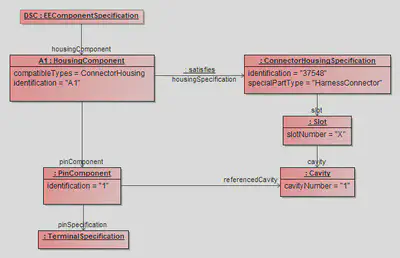
An E/E-Component is represented in the VEC by an EEComponentSpecification. The connector interface of an E/E-Component is represented by a HousingComponent. The HousingComponent separates into two aspect:
- Geometrical: It references a
ConnectorHousingSpecificationto describe the geometrical / mechanical properties of the connector, e.g. the shape, slot layout, number of cavities etc. As this is the sameSpecificationthat is used for harness connectors it just defines an empty housing, without pins and terminals. - Electrical: The electrical properties of the connector, the actual pins in the housing, are represented by the
PinComponent. The physical properties of the pin are represented by aTerminalSpecification.
The figure Instantiation Example shows the structure for an E/E component with a single pin. The following XML listing shows the same as xml snippet:
<Specification xsi:type=vec:EEComponentSpecification" id"id_ecomponent_spec_1498">
    <Identification>DSC</Identification>
    <DescribedPart>...</DescribedPart>
    <HousingComponent id="id_housing_comp_1500">
        <Identification>A1</Identification>
        <HousingSpecification>id_connect_hous_spec_1501</HousingSpecification>
        <PinComponent id="id_pin_comp_1506">
            <Identification>1</Identification>
            <PinSpecification>id_terminal_spec_1511</PinSpecification>
            <ReferencedCavity>id_cavity_1504</ReferencedCavity>
        </PinComponent>
    </HousingComponent>
</Specification>
<Specification xsi:type="vec:ConnectorHousingSpecification" id"id_connect_hous_spec_1501">
    <Identification>37548</Identification>
    <SpecialPartType>HarnessConnector</SpecialPartType>
    <Slot xsi:type="vec:Slot" id"id_slot_1502">
        <SlotNumber>A</SlotNumber>
        <Cavity id="id_cavity_1504">
            <CavityNumber>1</CavityNumber>
        </Cavity>
    </Slot>
</Specification>
<Specification xsi:type="vec:TerminalSpecification" id"id_terminal_spec_1511">
    <Identification>Usn3B323a4a10a614881C33</Identification>
    ...
</Specification>
Connector / Interface Types
Note: This section is in particular relevant for component boxes, as they have the greatest variance of different interface types. However, all these interface types can as well appear in other EE components. To understand the technical background and the definition of the different types, please read the article about Component Boxes
All (pluggable) electrical interfaces of a EE component to other components or the harness are
represented by a HousingComponent. That means for each fuse, multi fuse or relay
slot and for all pluggable harness connectors or direct contacting connectors a HousingComponent
is defined.
Each HousingComponent references a ConnectorHousingSpecification that defines the geometrical properties of the slot.
Version < 1.2.0: The classification of the housing component (e.g. is it a fuse or relay slot) is done with the
specialPartType of the associated ConnectorHousingSpecification.
Version >= 1.2.0: VEC 1.2.0 introduced a compatibleTypes attribute in the HousingComponent
to define what type of components are valid counter parts for a housing component. This is considered as an additional
information to the pre 1.2.0 way.
Note: Slots for multi fuses are also represented by one HousingComponent.
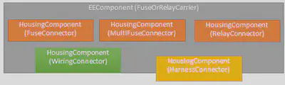
| Type of Slot | ConnectorHousingSpecification.SpecialPartType (V1.1.3) | HousingComponent.CompatibleTypes (V1.2.0) |
|---|---|---|
| Fuse slot | FuseConnector | Fuse |
| Multi fuse slot | MultiFuseConnector | MultiFuse |
| Relays slot | RelayConnector | Relay |
| Direct Contacting | WiringConnector | Terminal |
| Slot for Harness Connector | HarnessConnector | ConnectorHousing |
| Slot for Ring Terminals of a Harness | HarnessConnector | RingTerminal |
| Modular Slot for other E/E-Components | … | EEComponent |
In figure E/E-Component Interfaces the instantiation of such a structure is partially shown. The details of a
connector description with Slot, Cavity and PinComponent are
only implied on the left side.
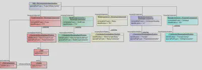
The listing below shows the general xml structure for such a component box. Omitted blocks are marked with “…”.
<Specification xsi:type="vec:EEComponentSpecification" id"id_ecomponent_spec_1463">
  <Identification>Dnq3202104816a236</Identification>
  <SpecialPartType>FuseOrRelayCarrier</SpecialPartType>
  <DescribedPart>id_part_ver_1419</DescribedPart>
  ...
  <HousingComponent id="id_housing_comp_1466">
      <Identification>B</Identification>
      <HousingSpecification>id_connect_hous_spec_1430</HousingSpecification>
      ...
  </HousingComponent>
  <HousingComponent id="id_housing_comp_1478">
      <Identification>G2</Identification>
      <HousingSpecification>id_connect_hous_spec_1459</HousingSpecification>
      ...
  </HousingComponent>
</Specification>

<Specification xsi:type="vec:ConnectorHousingSpecification" id"id_connect_hous_spec_1430">
  <Identification>WIRING</Identification>
  <SpecialPartType>WiringConnector</SpecialPartType>
  <Slot xsi:type="vec:Slot" id"id_slot_1432">
      ...
  </Slot>
</Specification>

<Specification xsi:type="vec:ConnectorHousingSpecification" id"id_connect_hous_spec_1459">
  <Identification>FUSE</Identification>
  <SpecialPartType>FuseConnector</SpecialPartType>
  <Slot xsi:type="vec:Slot" id"id_slot_1460">
      ...
  </Slot>
</Specification>
Internal Connectivity
Connections
This section applies to all kind of internal connections in E/E components. One of the major use cases for this is the representation of internal connectivity of component boxes, since this is an important information, for example for physical validation or the calculation of current flows in the network. The model elements can also be used to represent the internal connectivity of a relay or any other E/E component. However, when it comes to software enabled component states (e.g. ECUs) the feasibility is more than questionable.
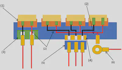
In figure Component Box Schematic Illustration the internal connections are illustrated by the red and black lines (2).
In terms of the VEC, an InternalComponentConnection defines a logical (conductive) connection between
a number of PinComponent within a E/E component. This representation does not consider the actual realization
of the conductivity. This means, when multiple pins are connected, that the representation in the model is the same whether it is
realized by point to point connections, a conductor rail or direct contacting.
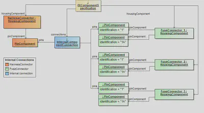
In figure Instancing for Internal Connections an instance diagram is shown for a power distribution connection between a supply on the left side and the individual fuse slots on the right side.
Note: The essential criteria for a InternalComponentConnection is the electrical conductivity. So even
if the connection in the example would be realized by three individual conductors between the left and the right side, it would be
represented by one InternalComponentConnection
Switching States
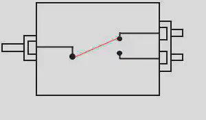
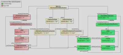
In figure Switching States Illustration a simple EEComponentSpecification with SwitchingState is schematically shown.
In figure Switching States the corresponding representation in VEC is shown. It is a simple switch with two states. In the example, the switch has two HousingComponent, meaning it has two connectors, one for the IN-side and one for OUT-side. The housing component for the IN-side has one PinComponent, the OUT-side has two of them. However, a real example could as well have just one HousingComponent with three PinComponent. The pin on the IN-side is connected to the pins on the OUT-side with a switchable XOR-connection.
The IN-side (highlighted in red) and the OUT-side (highlighted in green) are represented in the VEC as a connector interface of your choice, as described in Connector Interface / EE Component Header. In the VEC a InternalComponentConnection is free of variance, therefore each state of the XOR-connection of the example is represented by an individual InternalComponentConnection (A.1 -> B.1) and (A.1 -> B.2). The switch in this example has two switching states (B1 & B2), each referencing one InternalComponentConnection, meaning that if the state is active, the corresponding connections exist / have electrical conductivity. The fact, that B1 & B2 are mutally exclusive to each are other is currently not represented in the VEC.
Note: Without the additional information of the switching states, the representation with two InternalComponentConnection would be illegal, as it would semantically equivalent to representation with one InternalComponentConnection referencing three PinComponent