Component Boxes
Note: The following sections will cover the technical background about component boxes. The term “component box” will be used as a general term for all types of fuse and/or relay carrier, power distribution box etc. The detailed mapping of the different aspects on concepts of the VEC will be in EE-Components, as the concepts are the same for regular E/E components and component boxes.
Overview
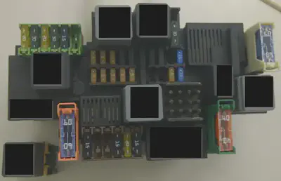
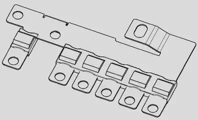
The image on the right side shows a photo of the front side of a component box. The drawing shows a drawing of a component box. In general, a component box is a component (carrier) that can be equipped with other components (e.g. relays & fuses) and by this, provides fusing and switching functionality to the attached wiring harness.
Basically a component box can be divided into four aspects:
- Slots to plug-in E/E components like fuses and relays.
- Connectivity with the wiring harness.
- Internal connectivity.
- Modularity
For all of these aspects, different technical solutions and variants exist. In reality, a specific component box can virtually combine and mix up all of these solution variants. To create a concise representation of a component box in the VEC model, a combination of different concepts is necessary. Some of these concepts are not exclusively for component boxes.
Plugability of E/E components
As mentioned before, a component box provides slots to plug-in other E/E-components. The following sections give brief overview of the most relevant types.
Fuse
A fuse is a component with two pins that can be plugged or screwed into a compatible fuse slot. There exists a wide range of different types that have individual triggering characteristics and currents, geometries, connection types etc.
Multifuse
A multi fuse is similar to a regular fuse. However, due to cost and packaging reasons multiple fuses are combined into a single component. The individual fuses share the power supply, see the multi fuse example.
Relais
A Relais is a component used for switching of loads and has more than 3 pins.
Direct and Indirect Contacting
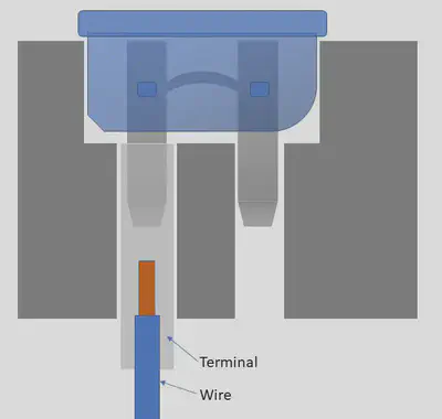
There are two different ways to create an electrical connection between the end of a wire and a corresponding fuse or relays, direct and indirect contacting. In case of direct contacting (see direct contacting) a terminal directly attached to the wire is locked into a cavity on ones side of the component box. The cavity goes through the component box and the pins of the fuse are directly plugged into the reception of the wire terminal. In this case, the component box itself does not provide a electrical conductivity.
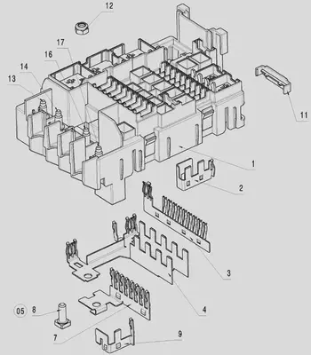
In case of indirect contacting the component box contains a conductor (e.g. a conductor rail) that connects multiple cavities of the component box, see #3, #4, #7 and #9 in the component box drawing. The pins of the fuse are plugged into receptions of the conductor rail. Same applies for the connection to the harness. The wire terminals are grouped together into a harness connector, which is then attached to the component box. The conductor rail is often used for implementing the power distribution on the input side of a component box. In this case, the connection to the wiring harness is often done with ring terminals attached to bolts of the component box, see #8, #13, #14 and #16 in the component box drawing.
A combination of both in one component box is possible (and likely), e.g. the supplying side is realized with a conductor rail (indirect contacting) and the protected side is realized with direct contacting.
Connectivity with the Wiring Harness
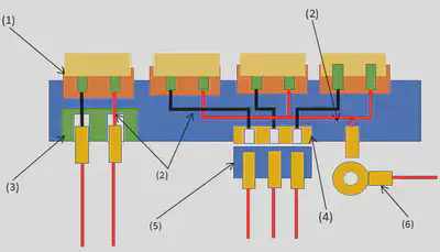
In case of direct contacting the component box itself serves as end point for the wires. Therefore the last topology segment is attached to the component box. The component box requires / provides segment connection points. From an abstract point of view and out of the perspective of the wiring harness, a component box with direct contacting behaves just like a regular harness connector, see the schematic illustration (3).
In case of indirect contacting the wires and terminals are clipped into a regular harness connector and the connector is plugged into the component box. So, again from an abstract point of view and out of the perspective of the wiring harness, the component box with indirect contacting and a harness connector behaves just like a regular E/E-Component (e.g. an ECU, an actor or a sensor), see the schematic illustration (4) & (5).
Another variant in case of indirect contacting is the usage of ring terminals. The component box provides a bolt and a wire is attached to it with a ring terminal. In this case the component box behaves like a battery or a ground bolt, see the schematic illustration (6) .
Internal Connectivity
For the calculation of current paths or electrical testing, a component box needs to define an internal connectivity, see the schematic illustration (2). This is a logical connectivity and it is irrelevant, if it is realized with direct or indirect contacting.
Modularity
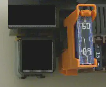
Some component boxes support modular concepts, e.g. the one shown in the photo. That means the component box can be extended with additional carriers, sockets or smaller component boxes (in a LEGO like way). There are two concepts for modularity: with or without electrical connectivity. If you compare the photo on top with the photo on the right you can see, that the relays socket in the lower left corner is mechanically clipped to main component box, electrically it is independent.
In contrast to this, the orange fuse socket right beside the relay socket has its upper part plugged into the main component box, with electric connectivity for power supply. The lower part of it provides an independent cavity for direct contacting of the protected side.