Pinning
Change History
| Id | Subject | Date |
| Latest Commit | Review notice removed after expiry of the objection period. | 2024-10-22 |
| KBLFRM-586 | Added explanations for PinComponentBehavior and SignalDirections & PinComponentTypes. | 2023-11-10 |
The following section contains examples for the definition of Pinning information in the VEC. This means the specification of the electrical behavior of PinComponents. Make sure you have read the chapter “Pinning Information & Pinning Variance” before.
PinComponentBehaviors
To define the electrical behavior of a PinComponent the PinComponentBehavior is used. It is possible, that a PinComponent has more has multiple behaviors, which are configuration dependent (e.g. software defined pins on an ECU). Therefore, the PinComponentBehavior is a ConfigurableElement. With a PinComponentBehavior various electrical characteristics of the pin can be described. The next sections contain examples for that.
PinComponentType and SignalDirection
The figure below illustrates three E/E-components in a power distribution scenario and the logical correlations between them. Please note that the illustration is an excerpt from the master data. Actual relationships would only be established during the use / instantiation e.g. in a wiring. This is taken into account in that the logical relationships are only indicated by dependencies (dashed arrows).
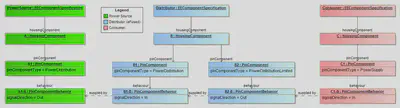
Our SPDS (Simple Power Distribution System :winking_face:) consists of the three components, a PowerSource (e.g. a Battery), a Distributor and a Consumer.
The PowerSource on the left side has a PinComponent with pinComponentType='PowerDistribution' and signalDirection='Out', because it distributes power to other components.
The Consumer on the right side has a PinComponent with pinComponentType='PowerSupply' and signalDirection='In', because the component itself is supplied with power over that pin.
The Distributor is software-defined eFuse in the example, it has two PinComponents. One “B1” is used to receive power, for distribution to others, therefore it is defined with pinComponentType='PowerDistribution' and signalDirection='In'. This should not be confused with pinComponentType='PowerSupply', which indicates that the received power is used to supply the component itself with energy. The second pin “B2” is defined with pinComponentType='PowerDistributionLimited' and signalDirection='Out'. This is because the pin is limited by an eFuse. For a conventional limitation (e.g. melting fuse) the fusing would be available via the internal connectivity of the E/E component and the pinComponentType='PowerDistribution' would be used.
Signal Peak Distance and Duration
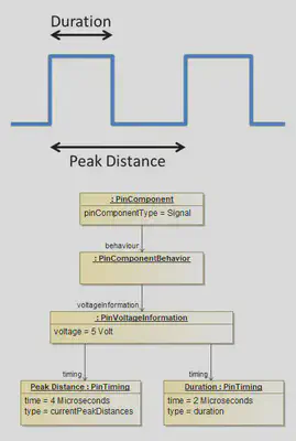
This example shows how a digital signal with pulse width and pulse separation can be defined. The PinComponentBehavior of a PinComponent has PinVoltageInformation. The PinVoltageInformation can define multiple PinTiming definitions. For pulsed digital signals, two PinTimings are used. One PinTiming (Duration) describes the pulse width. The other PinTiming (Peak Distance) describes pulse separation.
Load Type Dependant Maximum Current (Relais)
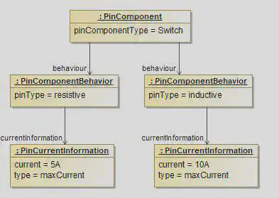
Dependant on the load type (inductive, resistive, capacitive) a switching contact of a relais can have different maximum loads.
The diagram shows a PinComponent of type switch that has two PinComponentBehaviors with pinType resistive and inductive. Each PinComponentBehavior has a PinCurrentInformation with type maxCurrent and different current values.