Coupling Devices
Change History
| Id | Subject | Date |
| Latest Commit | Removed review markers. | 2022-10-21 |
| KBLFRM-600 | Improved Implementation Guideline for coupling devices (and extracted to a separate page) | 2022-02-04 |
In the context of the VEC, a coupling device is:
… the (virtual) device that separates / connects two or more wiring harnesses. “Virtual” because it can be interpreted as a device / interface definition between the harnesses, where one harness behaves like an E/E component form the point of view of the other harness1.
That means, at a coupling device a larger electrical system is divided into multiple harnesses. There can be various reasons for such a division and depending on these reasons, coupling devices can be defined at different points in the development process. Often there are assembly requirements that make a subdivision necessary (e.g. between the door and main body). If an electrical connection is defined between those separate installation spaces, it crosses a coupling device and is split up at this point. Whether a connection crosses such a coupling device or not can often be only determined after the routing process in a concrete context of the packaging of a specific vehicle. Such coupling devices are often only relevant in a geometry / topology perspective and for the wiring of a specific harness and not in an architectural or system schematic layer.
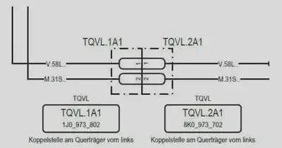
However, there are also coupling devices that serve other purposes and therefore, must be defined early in the electrological branches of the development processes, i.e. in the architecture layer or the system schematic. A schematic diagram of such coupling device can be found in the figure above and will be example for the following sections.
Basic Concept
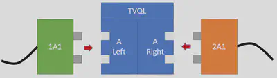
The basic idea for a mapping in the VEC for such coupling points between different harnesses is, to consider them as virtual E/E components with an internal connectivity. When looking at such a point on a real wiring harness, we will just see two or more connectors that are plugged into each other. However, the definition of a virtual component between these connectors in the product model creates multiple advantages:
- The representation in the system schematic is analogous to other E/E components. Traceability with the wiring layer can be achieved in a uniform way.
- When just looking at a single wiring harness, all connectors can be connected to an E/E component, no connectors are “hanging in thin air”.
- The virtual E/E component can be used as an interface contract and a point of separation between different development and process partners or even development lifecycles. For example, the wiring harness of a seat does not need to “know” everything about the complete electrical network of the vehicle. It just requires an interface definition of the E/E component “rest of the vehicle”.
- The virtual E/E component can be used to enforce standards for specific coupling points, for example a consistent pinning between the doors and the main body across multiple carlines.
System Schematic
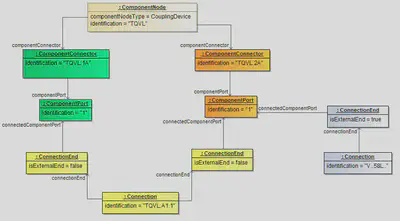
The figure above illustrates minimal representation of a coupling device in the system schematic with just one connector and only one pin on each side. The coupling device itself is represented in the VEC with a ComponentNode with the ComponentNodeType ='CouplingDevice'. For each side of the coupling device it contains a ComponentConnector. These connectors include the ComponentPorts, which represent the pins of the connector.
The connectivity between the port on each side is represented with a internal Connection with two ConnectionEnds, which reference the connected ComponentPorts. The flag isExternalEnd of the Ends is set to false, because the connection represents the internal mapping of ports within the coupling device. Connections to other ComponentNodes would be represented by different Connections with ConnectionEnds where isExternal=true.
Document Structure
Like with any self-contained piece of information in the VEC, for traceability reasons the definition of a _coupling device should be in the correct DocumentVersion. Section General Structure explains the general concept of DocumentVersion and their containments. As described there, the containment of Specifications in their DocumentVersions has a semantic meaning. The correct placement of a coupling device in a containing DocumentVersion is a perfect example for that.
Depending on the engineering process, system schematic relevant coupling device might be defined in some kind of master data process, enforcing standardized coupling devices for a specific scope. In that case, one or more of those standardized coupling devices would be managed and published together, and then reused in a specific system schematic. This is illustrated in the figure “Information Structure” below, on the left side of the figure.
On the other, it would also be perfectly valid to have no company wide management process for coupling devices. In this case, the coupling devices would be defined implicitly within a system schematic. This is illustrated on the right side of the figure.

XML Example
The XML snippet below contains the portions of a coupling device definition that belong to the system schematic layer.
<DocumentVersion id="id_docu_ver_16475">
  <Description xsi:type="vec:LocalizedString" id="id_16476">
    <LanguageCode>De</LanguageCode>
    <Value>Definition der Trennstelle TQVL</Value>
  </Description>
  <DocumentNumber>TQVL</DocumentNumber>
  <DocumentVersion>1</DocumentVersion>
  <DocumentType>MasterDataDefinition</DocumentType>
  <DataFormat>VEC</DataFormat>
  <Specification xsi:type="vec:ConnectionSpecification" id="id_connect_spec_1">
    <Identification>ConSpec_TZY5-DV12a</Identification>
    <ComponentNode id="id_comp_node_6">
      <Identification>TQVL</Identification>
      <ComponentNodeType>CouplingDevice</ComponentNodeType>
      <RealizedUsageNode>[id ref to usage node]</RealizedUsageNode>
      <ComponentConnector id="id_component_connector_1">
        <Identification>TQVL.1A</Identification>
        <ComponentPort id="id_component_port_1">
          <Identification>1</Identification>
        </ComponentPort>
      </ComponentConnector>
      <ComponentConnector id="id_component_connector_2">
        <Identification>TQVL.2A</Identification>
        <ComponentPort id="id_component_port_2">
          <Identification>1</Identification>
        </ComponentPort>
      </ComponentConnector>
    </ComponentNode>
    <Connection id="id_connection_1">
      <Identification>TQVL.A1</Identification>
      <ConnectionEnd id="id_conn_end_1">
        <Identification>TQVL.A.1</Identification>
        <IsExternalEnd>false</IsExternalEnd>
        <ConnectedComponentPort>id_component_port_1</ConnectedComponentPort>
      </ConnectionEnd>
        <ConnectionEnd id="id_conn_end_2">
        <Identification>TQVL.A.2</Identification>
        <IsExternalEnd>false</IsExternalEnd>
        <ConnectedComponentPort>id_component_port_2</ConnectedComponentPort>
      </ConnectionEnd>
    </Connection>
  </Specification>
</DocumentVersion>
Wiring
Traceability
Even without having an explicit coupling device definition (with a virtual E/E component) in the wiring layer, a traceability over a coupling device from one wiring harness to another is possible with the help of the system schematic layer.
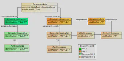
Taking the ComponentNode Definition from above as a foundation, it is only necessary to create the traceability relations from the harness connectors to the system schematic layer, as illustrated in the figure below.
Below is the corresponding XML snippet.
<Component id="component_1">
  <Identification>TQVL.1A1</Identification>
  <Role xsi:type="vec:ConnectorHousingRole" id="connectorHousingRole_1">
    <Identification>TQVL.1A1</Identification>
    <ConnectorHousingSpecification>connectorHousingSpecification_1</ConnectorHousingSpecification>
    <ConnectedComponentConnector>id_component_connector_1</ConnectedComponentConnector>
    <SlotReference xsi:type="vec:SlotReference" id="slotRef_1">
      <Identification>A</Identification>
      <ReferencedSlot>slot_1</ReferencedSlot>
      <CavityReference id="cavityRef_1">
        <Identification>1</Identification>
        <ReferencedCavity>cavity_1</ReferencedCavity>
      </CavityReference>
    </SlotReference>
  </Role>
  [...]
</Component>
<Component id="component_2">
  <Identification>TQVL.2A1</Identification>
  <Role xsi:type="vec:ConnectorHousingRole" id="connectorHousingRole_2">
    <Identification>TQVL.2A1</Identification>
    <ConnectorHousingSpecification>connectorHousingSpecification_2</ConnectorHousingSpecification>
    <ConnectedComponentConnector>id_component_connector_2</ConnectedComponentConnector>
    <SlotReference xsi:type="vec:SlotReference" id="slotRef_2">
      <Identification>A</Identification>
      <ReferencedSlot>slot_2</ReferencedSlot>
      <CavityReference id="cavityRef_2">
        <Identification>1</Identification>
        <ReferencedCavity>cavity_2</ReferencedCavity>
        <ConnectedComponentPort>id_component_port_2</ConnectedComponentPort>
      </CavityReference>
    </SlotReference>
  </Role>
  [...]
</Component>
<Component id="component_3">
  <Identification>TQVL.2A2</Identification>
  <Role xsi:type="vec:ConnectorHousingRole" id="connectorHousingRole_3">
    <Identification>TQVL.2A2</Identification>
    <ConnectorHousingSpecification>connectorHousingSpecification_2</ConnectorHousingSpecification>
    <ConnectedComponentConnector>id_component_connector_2</ConnectedComponentConnector>
    <SlotReference xsi:type="vec:SlotReference" id="slotRef_3">
      <Identification>A</Identification>
      <ReferencedSlot>slot_2</ReferencedSlot>
      <CavityReference id="cavityRef_3">
        <Identification>1</Identification>
        <ReferencedCavity>cavity_2</ReferencedCavity>
      </CavityReference>
    </SlotReference>
  </Role>
  [...]
</Component>
see
ComponentNodeType↩︎