System Schematic
Change History
| Id | Subject | Date |
| Latest Commit | Added "Transition to System Schematic" to "Architectural Layer Guideline" (#575) | 2025-11-06 |
| KBLFRM-1135 | Added Implementation Guideline for explicit potential distributors in the schematic context | 2021-11-30 |
| KBLFRM-790 | Added Implementation Guideline for inner structure of ComponentNodes | 2021-11-20 |
| KBLFRM-1142 | Added Implementation Guideline for innernal connectivity. | 2021-11-20 |
System Schematic Basics
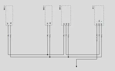
The system schematic is used to illustrate the electrical components (e.g. ECUs, sensors or switches) in a vehicle electrical system and their connections to each other on an electrological level without physical realization details. In many companies the system schematic is specific for an individual system and not an individual vehicle variant. The example below shows such a system schematic with four components (MX1.1, MX3.1, MX3.2 and E1.1), which are connected to each other in some way. On the connection lines the potential names can be found. Furthermore the component E1.1 is connected to additional elements on another sheet / in another system, which is suggested by the arrow on the very bottom. This is explained in more details in the section Partial Systems.
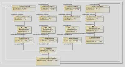
To represent a system schematic in the VEC the ConnectionSpecification and its subelements are used. E/E-Components (in some ECAD Systems called Block) are represented by ComponentNodes. A ComponentNode is a node where an electrological component is located. It is a representative for an element in the electric system, e.g. an actuator, a sensor, an ECU. This diagram contains the representation as VEC classes of the system schematic shown in the example. The ComponentPort (Pins) of a ComponentNode are grouped into Connectors / Slots with the help of ComponentConnectors. In the example the connectors are only represented implicitly by the prefix “A” to the Pin-Number.
Even if the system schematic in this example only shows pins which are connected to other pins (of other components), the VEC representation of the component (ComponentNode) is explicitly allowed to contain ComponentPorts for unused pins. For example a component with 5 pins where just pin no. 1 and 5 are connected in some way may contain ComponentPorts for the pins 2 - 4 (but is not required to). This underlines that these pins do physicaly exists. There is no need of a reference from a Connection to one of the ComponentPorts via a ConnectionEnd.
The following XML listing contains the component nodes and connection from the example above.
<Specification xsi:type="vec:ConnectionSpecification" id="id_connect_spec_1">
    <Identification>ConSpec_V..58L..</Identification>
    <ComponentNode id="id_comp_node_1">
        <Identification>MX1.1</Identification>
        <ComponentConnector id="id_component_connector_1">
            <Identification>A</Identification>
            <ComponentPort id="id_comp_port_1">
                <Identification>1</Identification>
            </ComponentPort>
        </ComponentConnector>
    </ComponentNode>
    <ComponentNode id="id_comp_node_2">
        <Identification>MX3.1</Identification>
        <ComponentConnector id="id_component_connector_2">
            <Identification>A</Identification>
            <ComponentPort id="id_comp_port_2">
                <Identification>1</Identification>
            </ComponentPort>
        </ComponentConnector>
    </ComponentNode>
    <ComponentNode id="id_comp_node_3">
        <Identification>MX3.2</Identification>
        <ComponentConnector id="id_component_connector_3">
            <Identification>A</Identification>
            <ComponentPort id="id_comp_port_3">
                <Identification>1</Identification>
            </ComponentPort>
        </ComponentConnector>
    </ComponentNode>
    <ComponentNode id="id_comp_node_4">
        <Identification>E1.1</Identification>
        <ComponentConnector id="id_component_connector_4">
            <Identification>A</Identification>
            <ComponentPort id="id_comp_port_4">
                <Identification>1</Identification>
            </ComponentPort>
        </ComponentConnector>
    </ComponentNode>
    <Connection id="id_connection_1">
        <Identification>V..58L..</Identification>
        <ConnectionEnd id="id_conn_end_1">
            <Identification>MX1.1-A1</Identification>
            <ConnectedComponentPort>id_comp_port_1</ConnectedComponentPort>
        </ConnectionEnd>
        <ConnectionEnd id="id_conn_end_2">
            <Identification>MX3.1-A1</Identification>
            <ConnectedComponentPort>id_comp_port_2</ConnectedComponentPort>
        </ConnectionEnd>
        <ConnectionEnd id="id_conn_end_3">
            <Identification>MX3.2-A1</Identification>
            <ConnectedComponentPort>id_comp_port_3</ConnectedComponentPort>
        </ConnectionEnd>
    </Connection>
    [...]
</Specification>
Potential Nodes
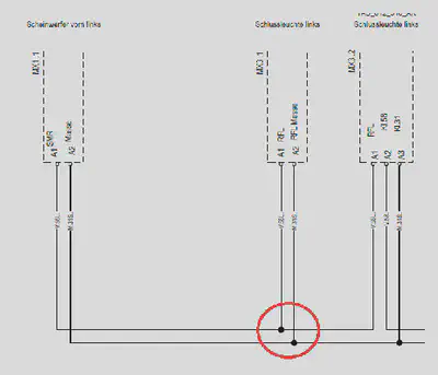
As mentioned before, the level of abstraction of the system schematic in the VEC (represented by the ConnectionSpecification) contains only the electrological design and no physical design of the wiring harness. Therefore, the black dots (circled in red) in the graphical example have only a layouting purpose and do not represent a technical design decision (e.g. to place a splice on this spot).
The expressed engineering intention is only that the connected pins (all “A1”) have the same potential (are connected in some way). The decision about a technical realization (e.g. splice, multicrimp, single wires) can not be made is most cases at the stage of a system schematic, because a technical realization depends on concrete variant combinations and might be even different for different variants (see section Wiring) or it can be unnecessary, because in a reduced 100% variant, there might be just two of the three components left and a realization with a single wire would be possible. As the VEC does not represent the graphical layout of documents these nodes have no representation in VEC.
If the system schematic should explicitly contain the engineering intention of a specific connection topology (e.g. a star like topology with a splice or a potential distributor) this must be explicitly represented by an individual design of one ore more ComponentNodes and Connections. Such a ComponentNode should have the ComponentNodeType = 'PotentialDistributor'. The illustrations below show the example of a CAN bus system with and without explicit distribution.


As you can see in the illustration of the central distributed CAN bus, the component node of the distributor “CAN” uses internal connections to represent the short-circuited pins. More information about internal conectivity can be found in this section below.
Partial Systems
During the development of individual systems or sub systems for a vehicle the corresponding system schematic is often incomplete (partial). This situation arises from the fact, that most systems depend on some kind of infrastructure of the integrated overall vehicle system (e.g. power, ground or bus connections), which is only a available in the context of the complete vehicle. In the example at the top such a link to an unspecified infrastructure is represented by the down arrow, in the following sections this is called an open link.
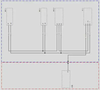
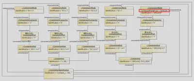
To create a fully functional system, a partial system must be merged / combined with other partial systems. In this process matching open links are connected (and thus removed) in order to create complete overall system. In the extended example this is illustrated by adding a second partial system schematic (framed in red) to the original example from the top. The resulting overall system schematic of such a merge process would just contain a simple connection between E.1.1 and M31.
The mapping of this advanced schematic example into the VEC context it is the following (see this diagram).
- To maintain the logical grouping of each partial system schematic, the content of each is contained in its own
DocumentVersionwith a singleConnectionSpecificationin the sameVecContent. - The open link is represented by a “virtual”
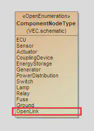
ComponentNode. Its naming is arbitrary and shall be choosen in a way, that a merge algorithm has the required information. For the clarity of the example it is here named GROUND. Depending on the used merge algorithm the name can be irrelevant if the merge algorithm for example only requires signal information. - The “virtual” component node shall be marked with the
ComponentNodeTypeliteral OpenLink (see on the right).
This diagram shows the extended version with the ComponentNode “GROUND”. As you can see the ComponentNode is marked with the node type “OpenLink” (red mark) to clarify that this component is NOT part of the system schematic but components from the plan DO HAVE a connection to it.
Caution: The strategy and algorithm to merge partial systems if individual for the different ECAD systems and development processes. The VEC does not define an algorithm or requires a specific strategy. The VEC only the means to store and exchange the information that is required by those algorithms. When merging the definition of these partial systems together into one vehicle system, it is mandatory to resolve these open links and replace them by determined ComponentNode elements or Connection:
- Case 1: The open link component node is replaced by a real component with the required connectivity.
- Case 2: If multiple real component nodes have connections to different open link component nodes, the open link nodes can be merged to a single connection among the real component nodes.
Note: It is possible to reference a ComponentPort from a Connection.ConnectionEnd even if they are contained in different DocumentVersions.
The following listing shows the additional ComponentNode as XML.
<Specification xsi:type="vec:ConnectionSpecification" id="id_connect_spec_1">
    <Identification>ConSpec_V..58L..</Identification>
    [...]
    <ComponentNode id="id_comp_node_4">
        <Identification>E1.1</Identification>
        <ComponentConnector id="id_component_connector_4">
            <Identification>A</Identification>
            <ComponentPort id="id_comp_port_4">
                <Identification>1</Identification>
            </ComponentPort>
        </ComponentConnector>
    </ComponentNode>
    <ComponentNode id="id_comp_node_5">
        <Identification>GROUND</Identification>
        <ComponentNodeType>OpenLink</ComponentNodeType>
        <ComponentConnector id="id_component_connector_5">
            <Identification>A</Identification>
            <ComponentPort id="id_comp_port_5">
                <Identification>1</Identification>
            </ComponentPort>
        </ComponentConnector>
    </ComponentNode>
    [...]
    <Connection id="id_connection_1">
        <Identification>GROUND..SYS_055A</Identification>
        <ConnectionEnd id="id_conn_end_1">
            <Identification>E1.1-A1</Identification>
            <ConnectedComponentPort>id_comp_port_4</ConnectedComponentPort>
        </ConnectionEnd>
        <ConnectionEnd id="id_conn_end_2">
            <Identification>GROUND-A1</Identification>
            <ConnectedComponentPort>id_comp_port_5</ConnectedComponentPort>
        </ConnectionEnd>
    </Connection>
</Specification>
Internal Connectivity
The system schematic layer in the VEC allows not only the mapping of Connections between different ComponentNodes, but also the mapping of internal connections within a ComponentNode. Examples are fuses, relays, power and potential distributors or fuse or relay carriers.

In the VEC these connections do not differ in modelling from ’normal’ ones in the level of abstraction of the system schematic. The only difference is the value of the flag isExternalEnd for their ConnectionEnds. The value of this flag has to be set from the ComponentPorts point of view and its relation to the Connection:
- If the
Connectionis attached from the outside to theComponentPort, e.g. it is a connection between two independentComponentNodes, then it isisExternalEnd = true. - If the connection is attached from the inside, e.g. it is a internal connection between two
ComponentPorts of the sameComponentNode, then it isisExternalEnd = false.
Inner Structure of Component Nodes
In the system schematic, components are often considered black boxes. However, there scenarios where this is not sufficient and a view on the inner structure is required. Therefore, ComponentNode can be structured hierarchically. This requirement is also the logical consequence of the concept of subdivided UsageNodes. Since ComponentNodes are representatives / realizations of UsageNodes, at least the same representation options are required here (see this implementation guideline for more details).
Sub ComponentNodes are located inside their parent node. Connections to the “outer world” are mostly realized via a ComponentConnector of the parent node and internal connectivity between the connector of the parent node and its children. The following graphic illustrates this situation. The internal connections are shown as red lines.

The “outer world” (e.g. a system schematic or a wiring harness) interacts only with the parent node (black box). However, there are use cases, e.g. after sales service, where it is relevant to know which element of the “outer world” (e.g. a wire or a pin) is connected to which sub node, e.g. “Which wire is the power supply of the direction indicator?”. The representation of this information in the VEC is explained in the following paragraphs.
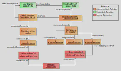
Both, parent node as well as child nodes are represented as ComponentNodes (highlighted in orange in the diagram above). The child ComponentNodes (e.g. “Low Light Node”) are contained in the parent ComponentNode (“Head Light Node”). A traceability to the corresponding UsageNode (highlighted in green) can be created with the realizedUsageNode association.
The parent and the child nodes define their electrical interface with ComponentConnectors and ComponentPorts. To represent the illustration, the parent node defines one ComponentConnector with three ComponentPorts, the child node defines one ComponentConnector with one ComponentPort. The internal connectivity is represented with a Connection between the ComponentPorts of the parent and the children (highlighted in red).
ConnectionEnds have different values for isExternalEnd. This is due to the fact that the end, that is connected to the port of the parent node, is on the inside (isExternal=false from the perspective of the port), the end that is connected to the inner node, is on the outside (isExternal=true).Variant Management For ECUs
This example demonstrates how the variant management can be handled in the systems schematic on different levels of abstraction.
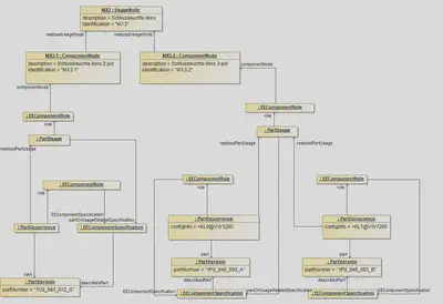
The top most element is the usage node. It defines an abstract position / function in the vehicle. In the example it is the back light on the left hand side (named “MX3”). This function can be realized by two different electrological variants (interfaces). These variants are represented by ComponentNodes. In the example there is one variant with two pins (MX3.1) and one variant with three pins (MX3.2). On a more concrete level these interfaces can be satisfied by one or more EE-components (alternatives). These EE-Components are defined by PartVersion with a EEComponentSpecification. In order to define restrictions a corresponding PartOccurrence with a VariantConfiguration can be defined.
The PartUsages in the example are needed for to reasons:
- They serve as a container to group the different possible alternatives (“realizedPartUsage”).
- It is necessary to declare one of the EEComponents as the representative of all alternatives of a variant. This is done by the reference between the PartUsage and the corresponding
EEComponentSpecification.