Wiring
Change History
| Id | Subject | Date |
| Latest Commit | KBLFRM-609/KBLFRM-1212: Added new implementation guideline für Coupling and Mapping | 2023-10-24 |
| KBLFRM-609 | Move coupling to the section 'product definition' | 2023-06-23 |
| KBLFRM-896 | Add description for traceability to System Schematic Connections for directly mated E/E Components | 2022-01-31 |
| KBLFRM-609 | Move contacting to the electrological layer wiring | 2021-11-24 |

The Wiring Layer in the VEC provides modeling concepts to define the physical realization of electrological connections from the System Schematic Layer. In the VEC, the same modeling concepts are use for this layer as for the mapping of a concrete wiring harness in the model.
However, in Wiring Layer representation the degree of freedom and number of unspecified facts are typically greater, than in a harness definition. For example the wiring layer would make statements about the cross section area of a wire or the color of its insulation, but it would not define a specific insulation material or wire length as the wiring layer is installation space agnostic in many development process.
Basically, there are three main modeling concepts:
- The description and instantiation of parts (e.g. connectors, wires, terminals).
- The contacting (marked with green dashed lines). It defines the relationship between terminals, wire ends and cavities.
- The coupling (marked with red dashed lines). This is for connecting connectors with E/E components or with each other, or even to connect E/E components with each other. It is explained in more detail in the guideline ““Coupling””
Description and Instantiation of Parts
In contrast to the Network Architecture and the System Schematic the Wiring Layer does not define its own level of abstraction, instead it utilizes the existing modeling concepts in the VEC to describe the physical properties of the electrologically relevant components.
It is possible to use concrete PartVersions in the Wiring Layer, but typically not all relevant properties are defined in the Wiring Layer, so mainly PartUsages will be used (detailed description can be found here).
Contacting
The contacting in the VEC defines the relationship between Cavities (CavityReference), WireEnds, Terminals and Seals. Since there are various types of contactings possible, the different types are not defined explicitly in the VEC. The VEC offers a quite generic structure (the Contacting), which should be able to support all the different possible types. This is necessary, because the different contacting types are driven by technical requirements and new contactings might emerge over the time. The downside of the generic structure is that the structural schema allows constellations that are not sensible from a technical point of view as well. The following sections show the different contacting types used today, and how they have to be implemented in the VEC.
Since the contacting can be used for different levels of abstraction (Product Definiton or Electrological Wiring) only the “Role-Side” of the necessary objects is shown. Necessary PartOrUsageRelatedSpecifications, PartOccurrences, PartUsages and PartVersion are omitted.
Standard Contact
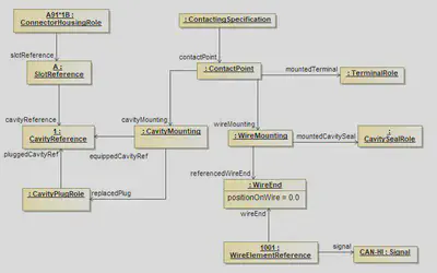
A standard Contacting is the most common case in a wiring harness. For a standard contact you have one wire end that has one terminal crimped on it, which is placed in one cavity. It exists in two variants, sealed and unsealed. The example displays the sealed variant, for the unsealed variant the CavitySealRole and the CavityPlugRole have to be omitted.
The contacting is defined by a ContactPoint, contained in a ContactingSpecification. It is possible (and recommended) to define multiple ContactPoints in one ContactingSpecification. Usally there exists one ContactingSpecification per DocumentVersion in the scope. So for example if the VEC-File represents a 150%-Harness definition, then you will have on ContactingSpecification for the complete harness.
A ContactPoint is defined as a point of exactly one electrical potential, which means all conducting components related to the ContactPoint are short-circuited.
The ContactPoint defines the terminal that is used for the contacting. It is then split up into two parts, the side of the crimp of the terminal (represented by the WireMounting) and the side of the terminal, which is placed in the cavity (represented by the CavityMounting). Since the example is about a sealed standard contact, the WireMounting displayed references exactly one CavitySealRole and one WireEnd, which means these two components are crimped together onto the terminal. On the other side the CavityMounting defines the Cavity in which the terminal will be placed. For a sealed environment it is necessary, that the Cavity is plugged with a CavityPlug, in case the Cavity is not occupied by a contacting. If the Cavity is occupied, the CavityMounting defines explicitly, which CavityPlugRoles are replaced by its existence.
Multi Crimp Contact
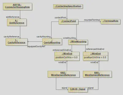
A Multicrimp is quite similar to the standard contact, with the difference that there is more than one wire crimped onto the terminal. Therefore the displayed example is quite the same. The differences are:
- There is no
CavityPlugRoleorCavitySealRole, since it is not usefull / possible from a technical point of view to seal a multicrimp. - There are two (or more)
WireEnds associated with theWireMounting.
For clarification of the example the two WireElementReferences reference their Signal. It is the same, since the two WireEnds are crimped onto one Terminal and therefore they are set to one single electrical potential. This is only displayed in the example in order to make it clear, what is meant by “A ContactPoint has one single electrical potential”. This is not a restriction of the VEC, since the development processes might need (or create) different signal names for the same electrical potential.
Ringterminal - Splice
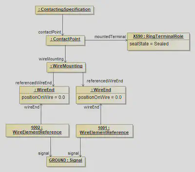
The structure displayed in the example applies to ring terminals and splices as well. On the side of the wire it is the same as a multi crimp. The difference is that no cavity mounting is used, since a ring terminal / splice has no cavities.
Bridge Terminal
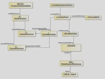
A bridge terminal is a terminal that has a wire crimped on it and which occupies more than one cavity (short-circuited). On the side of the wire it is the same as a standard contact. On the side of the cavities it simply references more than one cavity.
Coax Contact
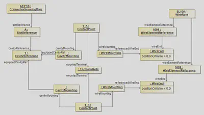
The diagram displays the proper definition of a coax contacting. In the case of coax contact one single terminal is used, but two different electrical potentials are connected to it. Therefore two ConcactPoints are required, because one ContactPoint can only be used for one electrical potential (see the definition of a ConcactPoint).
Both ContactPoints reference the same occurrence of the terminal (TerminalRole) and use the Cavity. Each ConcatPoint mounts a single WireElement to the TerminalRole. In this example the two WireElements belong to the same multi-core wire.
In order to make the example more clearly, the next figure displays the definition of such a “coax-cavity” in an EEComponent.
Coax Cavity
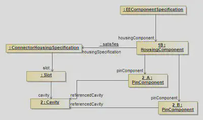
The HousingComponent of an EEComponent defines on one hand the pins (electrological relevant information) in this HousingComponent and on the other hand a ConnectorHousingSpecification (the layout and design of the HousingComponent). The PinComponents are then positioned in the cavities. In the case of a coax contact, two PinComponents (the different electrical potentials) are placed in one cavity.
The HousingComponent of an EEComponent defines on one hand the pins (electrological relevant information) in this HousingComponent and on the other hand a ConnectorHousingSpecification (the layout and design of the HousingComponent). The PinComponents are then positioned in the cavities. In the case of a coax contact, two PinComponents (the different electrical potentials) are placed in one cavity.
Direct Connectivity
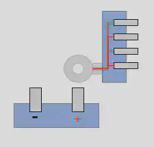
As is to be expected for the design of wiring harnesses, most of the electrological connections of a system schematic are realized by wires. However, there are also cases where such connections are also realized without wires, e.g. with a direct screwing connection or simple plugging of two E/E components. The most common use case of such directly connected components are fuses which are plugged into a slot of a fuse carrier. Another example is the battery isolator (German: “Batterietrennelement”), illustrated on the right side. The battery isolator is connected directly to the battery with an integrated ring terminal, that is screwed onto the bolt of the battery. The representation of this szenario is explained in the following paragraphs.
Mapping in the Wiring Layer
Each of the E/E component instances is build up in the same way as seen in this diagram. A EEComponentRole has got one or more HousingComponentReferences with underlying PinComponentReferences for the pins. To make statements about the technical details of such a pin, a TerminalRole is used.
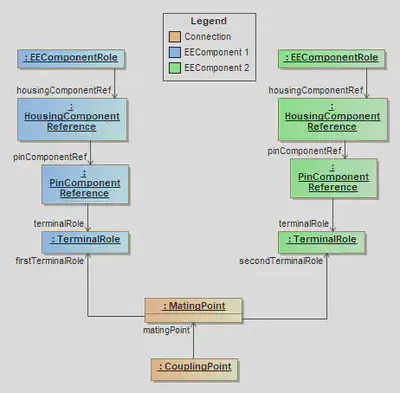
For the electrological connection / mapping of two pins, a MatingPoint is required, which creates the relation between the corresponding TerminalRoles. The MatingPoints are contained within a CouplingPoint in the CouplingSpecification. A CouplingPoint contains all MatingPoints for a single HousingComponentReference / ConnectorHousingRole (a detailed description can be found in the recommendation chapter Coupling Specification).
Note: In case of a terminal with multiple terminal receptions (with the possibility of separated potentials) a MatingDetail shall be used to define the mapping between specific TerminalReceptionReferences.
A detailed description of E/E components can be found in this tutorial.
Traceability to the System Schematic Layer
The system schematic layer contains no details about the physical realization. Therefore, no distinction is made in the system schematic layer between direct connections and wired connection. It is even possible to have different realizations of the same system schematic, one with a direct connection and one with a wired connection.
A detailed description to the system schamtic layer can be found in this tutorial.
To preserve traceability between the wiring layer and the system schematic, the element that realizes the the Connection has a reference to it. For a wired connection, this is the WireElementReference. In case of a direct connection, this is the MatingPoint or MatingDetail, depending on which level an unambiguous statement can be made. The following XML excerpt contains an example of traceability.
<Specification xsi:type="vec:CompositionSpecification" id="id_composition_1">
    <Component id="id_component_1">
        <Identification>Battery</Identification>
        [...]
        <Role xsi:type="vec:EEComponentRole" id="id_ee_role_1">
            <Identification>Battery</Identification>
            <EEComponentSpecification>id_ecomponent_spec_1</EEComponentSpecification>
            <HousingComponentRef id="id_housing_comp_ref_1">
                <Identification>A</Identification>
                <HousingComponent>id_housing_comp_1</HousingComponent>
                <ConnectorHousingRole id="id_conHousingRole_1">
                    <ConnectorHousingSpecification>id_connect_hous_spec_1</ConnectorHousingSpecification>
                    <SlotReference xsi:type="vec:SlotReference" id="id_slotRef_1">
                        <ReferencedSlot>id_slot_1</ReferencedSlot>
                        <CavityReference id="id_cavityRef_1">
                            <Identification>1</Identification>
                            <ReferencedCavity>id_cavity_1</ReferencedCavity>
                        </CavityReference>
                        [...]
                    </SlotReference>
                </ConnectorHousingRole>
                <PinComponentRef id="id_pin_comp_ref_1">
                    <PinComponent>id_pin_comp_1</PinComponent>
                    <TerminalRole xsi:type="vec:TerminalRole" id="id_terminalRole_1">
                        <Identification>1</Identification>
                        <TerminalSpecification>id_terminal_spec_1</TerminalSpecification>
                    </TerminalRole>
                </PinComponentRef>
                [...]
            </HousingComponentRef>
        </Role>
    </Component>
    <Component id="id_component_2">
        <Identification>Isolator</Identification>
        [...]
        <Role xsi:type="vec:EEComponentRole" id="id_ee_role_2">
            <Identification>Isolator</Identification>
            <EEComponentSpecification>id_ecomponent_spec_2</EEComponentSpecification>
            <HousingComponentRef id="id_housing_comp_ref_2">
                <Identification>A</Identification>
                <HousingComponent>id_housing_comp_2</HousingComponent>
                <ConnectorHousingRole id="id_conHousingRole_2">
                    <ConnectorHousingSpecification>id_connect_hous_spec_1</ConnectorHousingSpecification>
                    <SlotReference xsi:type="vec:SlotReference" id="id_slotRef_2">
                        <ReferencedSlot>id_slot_2</ReferencedSlot>
                        <CavityReference id="id_cavityRef_2">
                            <Identification>1</Identification>
                            <ReferencedCavity>id_cavity_2</ReferencedCavity>
                        </CavityReference>
                    </SlotReference>
                    [...]
                </ConnectorHousingRole>
                <PinComponentRef id="id_pin_comp_ref_2">
                    <PinComponent>id_pin_comp_2</PinComponent>
                    <TerminalRole xsi:type="vec:TerminalRole" id="id_terminalRole_2">
                        <Identification>1</Identification>
                        <TerminalSpecification>id_terminal_spec_2</TerminalSpecification>
                    </TerminalRole>
                </PinComponentRef>
            </HousingComponentRef>
            [...]
        </Role>
    </Component>
</Specification>
[...]
<Specification xsi:type="vec:CouplingSpecification" id="id_coupling_1">
    <CouplingPoint>
        <Identification>Battery-Isolator</Identification>
        <FirstConnector>id_conHousingRole_1</FirstConnector>
        <SecondConnector>id_conHousingRole_2</SecondConnector>
        <MatingPoint>
            <Identification>Mating-Battery-Isolator</Identification>
            <FirstTerminalRole>id_terminalRole_1</FirstTerminalRole>
            <SecondTerminalRole>id_terminalRole_2</SecondTerminalRole>
            <Connection>id_connection_1</Connection>
        </MatingPoint>
    </CouplingPoint>
</Specification>
[...]
<Specification xsi:type="vec:ConnectionSpecification" id="id_connect_spec_1">
    <Identification>ConSpec</Identification>
    <Connection id="id_connection_1">
        <Identification>PowerDistribution</Identification>
        <ConnectionEnd id="id_conn_end_1">
            <Identification>Battery</Identification>
            <ConnectedComponentPort>id_comp_port_1</ConnectedComponentPort>
        </ConnectionEnd>
        <ConnectionEnd id="id_conn_end_2">
            <Identification>Isolator</Identification>
            <ConnectedComponentPort>id_comp_port_2</ConnectedComponentPort>
        </ConnectionEnd>
    </Connection>
    [...]
</Specification>