Usage Nodes
Change History
| Id | Subject | Date |
| Latest Commit | Review disclaimer removed | 2022-03-01 |
| KBLFRM-790 | Added examples for the use of sub usage nodes | 2021-11-20 |

The example illustrates the use of UsageNodes. A UsageNode represents a position in an abstract vehicle. For example the Head Light Left. UsageNodes belong to the master data and they are defined on some company wide level. They can be used to enforce consistent naming over different projects and different development streams (e.g. between geometry and electrologic).
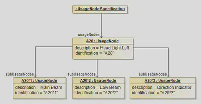
A UsageNode can be subdivided into more detailed UsageNodes. For example the Head Light can be split up into Main Beam, Low Beam and Direction Indicator.
The diagram above shows this usage of sub usage nodes. There is one main usage node “A20” with it’s sub nodes “A20*1”, “A20*2” and “A20*3”. For simplification of the following code snippet only the XML representation of the definition of the parent usage node “A20” and its child node “A20*1” is shown.
<Specification xsi:type="vec:UsageNodeSpecification" id="id_usage_node_spec_1">
  <Identification>UsageNodeList</Identification>
  <UsageNodes id="id_usage_node_1">
    <Identification>A20</Identification>
    <Description xsi:type="vec:LocalizedString" id="id_1">
      <LanguageCode>En</LanguageCode>
      <Value>Head Ligth left</Value>
    </Description>
    <SubUsageNodes>id_usage_node_2</SubUsageNodes>
  </UsageNodes>
  <UsageNodes id="id_usage_node_2">
    <Identification>A20*1</Identification>
    <Description xsi:type="vec:LocalizedString" id="id_2">
      <LanguageCode>En</LanguageCode>
      <Value>Main Beam</Value>
    </Description>
  </UsageNodes>
[...]
</Specification>