Placements and Dimensions
A Placement defines the way how a component is associated to the topology. The following sections contain examples about the different types of placements.
Simple WireProtection
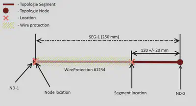
This diagram illustrates the placement of a simple WireProtection as shown in next diagram.
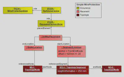
The Figure above displays the placement of a simple wire protection. The PartOccurrence is placed with an OnWayPlacement via a PlaceableElementRole. This means the placed component covers a linear area of the harness topology. The start and the end of this area is defined with two Locations. In the shown situation the StartLocation is a SegmentLocation, which means the start is somewhere in the middle of a TopologySegment. It is defined to be at 120mm measured from the EndNode of the TopologySegment. The EndLocation of the WireProtection is located on a TopologyNode with a NodeLocation. It is not valid to define Locations with SegmentLocation, which could be also expressed by NodeLocations. This means for SegmentLocations an offset of 0 or equal to the segment length is illegal.
Since the offset is NumericalValue it can have an optional Tolerance.
WireProtection with Dimension
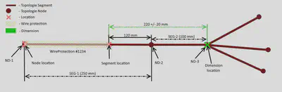
This diagram shows the previous example extended with a Dimension. In the previous example, the beginning of the WireProtection was defined with a tolerance value. This method is applied, if the tolerance is applied to the next TopologyNode (Start- or End-Node of the segment).
In many cases, tolerances are defined relative to specific points (e.g. points that can be measured) somewhere in the topology. In these cases a Dimension is used to defined the tolerance.
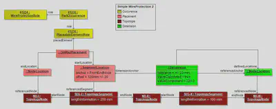
The placement of the WireProtection is just the same as in the previous example. It is extended with the Dimension (highlighted in green). The Dimension defines the tolerance of +/- 20mm between the TopologyNode ND-III and the beginning of the WireProtection.
The fact, that the Dimension is specified between the TopologyNode and the beginning of the WireProtection is expressed, that the TopologyNode is referenced directly (with a NodeLocation contained by the Dimension). The SegmentLocation used as DimensionAnchor is the same as used for the placement of the WireProtection.
The valueCalculated=true flag of the Dimension indicates that the valueComponent (220mm) is a derived an calculated value and not a user defined value. This value can be obtained from the placement information and the lengths of the TopologySegment.
Fixing Placement
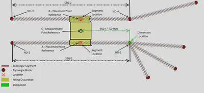
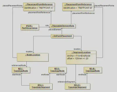
This diagram illustrates a more complex placement situation, including the usage of dimension.
The illustration shows a bracket, that is placed independently on two Segments (SEG-1 & SEG-2). The two points where the bracket is placed on the TopologySegments are identified separately (PlacementPointReference A & B). Additionally a Dimension is added, which gives a Tolerance between a geometric point (e.g. a bolt) on the bracket (MeasurementPointReference C) and a Node (ND-1) in the Topology (see TopologyNode).
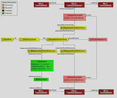
The diagram illustrates the instantiation of the example in the preceding diagram. Since the PartOccurrence can be placed in the topology, it has a PlaceableElementRole (with a corresponding PlaceableElementSpecification not shown in the diagram). The points where it can be placed onto the topology are represented by the PlacementPointReferences A & B. The point which can be used as anchor for a dimension (which can be any reference point on the component), is represented by the MeasurementPointReference C.
The actual placement is done with an OnPointPlacement which has two SegmentLocations. One for each PlacementPointReference.
Large Area WireProtections
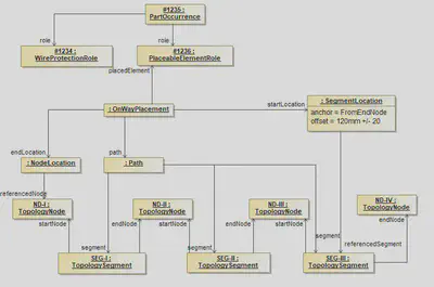
In some cases it is necessary to place a wire protection over a greater area of the topology, consisting of more than one TopologySegment (e.g. Tubes with a fixed length). For these cases the OnWayPlacement defines two locations for the start and the end and a path along which the wire protection is placed. The path is an ordered list of the segments from the start to the end. If a SegmentLocation is used for the start or the end the path must contain these segments as well.
For each TopologySegment the use of Start- and End-Node has no semantik relevance. The names are just used to make it possible to identify the corresponding TopologyNodes correctly e.g. when defining the anchor for a SegmentLocation.
Fixed Components (Single Location)
Fixed components are elements that are placed on a certain point in the topology, such as Connectors, Fixings and so on. These components are placed with an OnPointPlacement as shown in the example. If the Component has to be placed on a Node (e.g. a Connector) a NodeLocation is used. If the Component has to be placed on a Segment a SegmentLocation is used. The usage and constraints for the Locations are the same like the ones for OnWayPlacements.
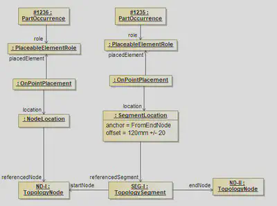
Fixed Components (Multiple Locations)
Some components, for example channels or a large connector with more than one segment connection point, may be placed on multiple positions in the Topology. For example a channel can have two or more reference points (e.g. the outlets) that must be associated to the different positions topology. In these cases an OnPointPlacement with more than one location is used. In order to identify which location places which point of the component (e.g. the outlets), a PlaceableElementRole can define PlacementPointReferences which are creating a relationship to the component description.
Default Dimensions
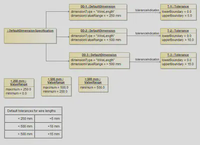
The diagram illustrates the use of a DefaultDimensionSpecification. The DefaultDimensionSpecification can be used to specify default dimensions / tolerances for certain attributes and ValueRanges. In this examples the Specification is used for the length of wires. (indicated by the dimensionType). The dimensionValueRange defines for which value’s of this type, the referenced Tolerance is applicable.
In this example for a wire length lower than 250 mm a Tolerance of +5 mm is allowed, for values between 250 mm and 500 mm a Tolerance of +10 mm is allowed and for everything above 500 mm a Tolerance of 15 mm is allowed.