VEC Implementation Guidelines
The VDA recommendation 4968 / prostep ivip recommendation PSI21 “Vehicle Electric Container (VEC)” defines an information model, a data dictionary, a XML schema and a RDF onthology derived from and compliant to the model.The intention of the model was to cover a wide range of use cases and application scenarios. For this reason the specification had to be kept generic in some degree and in some aspects. However, for specific scenarios and / or use cases a more detailed description on “how the different pieces fit together” is possible.
To avoid dialects in the different VEC implementations, further guidelines or recommendations are necessary. This collection of implementation guidelines contributes to the unambiguous interpretation of the VEC standard. For various wiring harness definition or electrical system aspects and scenarios the correct instantiation is shown and specific hints for correct usage are given.
Contributing and Proposals
If you find any bugs in the implementation guidelines or if you have a request for a specific topic, or if you would like to contribute your own tutorials please drop us an issue on the GitHub Issue Tracker. For more information please read our “Contribution Guideline”.
Additional Resources
Latest Changes
The following table contains lately changed pages, sorted descending by last change.| Title | Latest Content Addition / Commit | Created | Changed |
| Tapes and Tubes | #913: Initial version, specifically addressing the utilization of ProtectionGroups Latest Commit: Added a full page for tapes & tubes and explaining specifically the wireprotectiongroup (#956) | 2026-01-28 | 2026-01-29 |
| General Structure of VEC Files & Documents | #956: Added section on 'Content from mixed Sources' Latest Commit: Added section about content from mixed sources (#956) | 2020-06-22 | 2026-01-28 |
| Placements and Dimensions | Clarified semantic difference between SegmentLocation and NodeLocation. Latest Commit: Complete rework of wire protections after clarification of Node- & SegmentLocations (#935) | 2019-03-11 | 2026-01-28 |
| Splices | KBLFRM-855: Splice: Number of wires from the left / number of wires from the right Latest Commit: Complete rework of wire protections after clarification of Node- & SegmentLocations (#935) | 2022-11-09 | 2026-01-28 |
| Files, Partitioning, Sizing & Packaging (XML) | #1144: Added recommendation for file extension and IANA Media Types of VEC files. Latest Commit: Removed review note as decided in meeting 2026-01-16 | 2024-03-14 | 2026-01-23 |
| Instances of Components | #484: Added example for PartSubstitutionSpecification Latest Commit: Removed review note as decided in meeting 2026-01-16 | 2022-10-07 | 2026-01-23 |
| Topological Protection Requirements | #1138: Added guideline for topology zone requirements. Latest Commit: Removed review note as decided in meeting 2026-01-16 | 2025-12-08 | 2026-01-23 |
| Product Definition of a Harness | #1036: Content of a HarnessDescription Latest Commit: Clarified some passages. | 2022-09-01 | 2026-01-23 |
| Internal Connectivity | #915: New generic concept for E/E component with internal connectivity. Latest Commit: Removed review annotations. | 2025-07-08 | 2025-12-08 |
| Connectors | #957: Improved cavity mapping for modular connectors. Latest Commit: Removed review annotations. | 2018-11-29 | 2025-12-08 |
General Guidelines
This section contains guidlines and explanations for general concepts that apply universally to the VEC and which are not limited to specific model elements or use cases. Therefore they not contained in the model specification, or in more specific implementation guidelines. These guidelines shall be followed for all VEC implementations.
XML / XSD Representation
Mapping of UML VEC Model to XML Schema Definition (XSD)
The mapping of the VEC model to an XML schema definition (XSD) described in the following defines the standardized syntax for the exchange of harness design data across process steps and supporting tools.
The dedicated namespace prefix of the schema definition is vec, the namespace is http://www.prostep.org/ecad-if/2011/vec.
The XSD defines a single VecContent-element as xs:element. This is the declared root element for all VEC compliant XML-documents. A VEC compliant XML-document is limited to one instance of a VecContent.
Classes
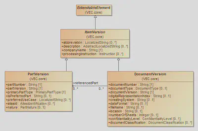
Each VEC UML model class (see figure below for an example from the VEC), which is not stereotyped as <<enumeration>>, are mapped in the following form.

- Each regular UML class is mapped to a
xs:complexTypewith the same name as the VEC model class name. - If the VEC model class is a derived subclass the corresponding
xs:complexTypedefines axs:extension. - VEC model class attributes & associations which are defined by the class itself and not inherited, are mapped to a
xs:sequenceofxs:elementswith the same names as the names of the corresponding class attributes (see Attributes and Associations below).
 <xs:complexType name="DocumentVersion">
      <xs:complexContent>
         <xs:extension base="vec:ItemVersion">
            <xs:sequence>
               <xs:element name="DocumentNumber" type="xs:string"/>
               <xs:element name="DocumentType" type="vec:DocumentType" minOccurs="0"/>
               ...
               <xs:element name="DocumentClassification"
                           type="vec:DocumentClassification"
                           minOccurs="0"
                           maxOccurs="unbounded"/>
               <xs:element name="ReferencedPart" type="xs:IDREFS" minOccurs="0"/>
               ...
            </xs:sequence>
         </xs:extension>
      </xs:complexContent>
   </xs:complexType>
Identifiers
id-Attributes
All xs:complexType that are not a refinement of another type (via xs:extension) define a mandatory XML attribute id with the type xs:ID. Syntax restrictions and uniqueness constraints for xs:ID are defined by the XML standard itself. xs:ID values are required to be unique within a XML document. Assocations between objects within a VEC XML document are defined with the help of xs:IDREF(S). The values in a xs:IDREF(S) must be defined xs:ID values existing in the context of the document.
The values for the id-attributes are normally generated by exporter / XML processor during the XML file generation. Exporters are expected to generate valid values for the id-attributes so that Links (instances of associations) are expressed correctly and the resulting XML file is XSD compliant.
   <xs:complexType name="ExtendableElement" abstract="true">
      <xs:sequence>
      ...
      </xs:sequence>
      <xs:attribute name="id" type="xs:ID" use="required"/>
      <xs:attribute name="immutable-global-iri" type="xs:anyURI"/>
   </xs:complexType>
id-attributes have temporary character. By this recommendation exporters are not required to remember values they have once created during an export. Exporters are explicitly allowed to assign different values for the id-attributes during every export process.immutable-global-id-Attributes
As defined in the section above, each xs:complexType defines a XML-Attribute id with the type xs:ID, either by itself or by inheritance from a superclass. By nature, those ids are volatile and have a purpose only within a specific XML file.
However, there are requirements in advanced use cases where it is necessary to be able to identify objects in the VEC globally and in a temporally stable manner. Such use cases are for example, but not limited to:
- Change Management & Synchronization
- Integration with other Standards, e.g. the Asset Administration Shell (AAS)
- Provision of VEC objects via modular APIs (e.g. REST)
- Compliance with other serialization formats like RDF.
Therefore, each xs:complexType that defines an id-attribute also defines an immutable-global-iri attribute with the type xs:anyURI. Despite its name xs:anyURI is in fact the type for an Internationalized Resource Identifier (IRI), see “W3C XML Schema Definition Language (XSD) 1.1 Part 2: Datatypes”.
If two VEC objects, regardless of their context or their affiliation to a specific file, have the same immutable-global-iri, they are in fact a representation of the same (real world) object (potentially in a different state).
The concept of IRIs allows the definition of global unique identifiers in various ways and with different strategies. For example, using http-IRIs allows the dereferencing (finding) of objects identified by such IRIs. However, the chosen strategy has a strong influence on the circumstances under which two objects in the VEC can be identified as the same. Both effects (same & not the same) can be desired effects in a specific use case / process / scenario. Therefore, this recommendation does not define a specific strategy for minting IRIs for VEC objects. It is also beyond the scope of this recommendation to describe or define valid strategies for minting IRIs.
However, two examples shall illustrate the influence of a choosen strategy. The examples are for illustrative purposes only and their description does not claim to be complete:
- UUIDs: IRIs can be created from UUIDs. UUIDs are generated random values that guarantee universal uniqueness. To satisfy the requirement of temporal stability, a source system has to maintain (store) those UUIDs for every object. Objects that are created and distributed at the same time in different locations are hard to handle. Objects deleted from the system (and then recreated) are always handled as different objects.
- Calculated IDs: IDs could be calculated from object keys in the domain (e.g. the identifying attributes of a
PartVersion). Such IDs could be calculated on the fly and do not have the requirement to be stored along with the object, as they are stored implicitly via the attributes from which they are derived. If the same object (same identifying attributes) is created in different locations, both variants can still be recognized as identical. On the downside, an ID generation algorithm has to be defined, that generates those unique IDs for every possible object type and situation. The algorithm has to guarantee that the generated IDs fulfill uniqueness requirement, which depends on the naming / identification strategy of the process. And yet, there are still cases where objects can not be recognized as the same (e.g. renaming of “key”-attributes).
Attributes & Associations
In the XML Schema represention of the VEC, attributes and compositions are handled in the same way. The containing (or orginating) class defines a xs:element. The name-attribute of the xs:elementis equivalent to the name of the attribute or the target role in the UML model. The first letter is converted to upper case. The type of the xs:element is either a primitive type (see mapping below) or a reference to corresponding VEC schema type.
All associations in the VEC model are directed and therefore have a defined source and target. An association is mapped to an xs:element which is owned by the XSD complex type that represents VEC model class that is source of the association. The name of the element is equal to the name of the association target role name (first letter upper case). The type is xs:IDREF respectively xs:IDREFS depending on the associations target cardinality.
xs:IDREF(S) does not ensure typesafety of assocations. Meaning, that the only enforced constraint for values of a xs:IDREF(S)-elements by XML Schema is, that the value must be defined as an xs:ID somewhere within the document.
So any association pointing to any object within a VEC XML document will successfully pass a schema validation. However, it might violate type constraints imposed by the underlying UML model, resulting in a document not being VEC compliant, despite that fact that it is schema valid.
Primitives
The UML uses sereval primitive data types that are mapped to the correspondig XSD data types:
xs:string(corresponding to the VEC model data type definition String)xs:dateTime(corresponding to the VEC model data type definition Date)xs:integer(corresponding to the VEC model data type definition Integer)xs:double(corresponding to the VEC model data type definition Double)xs:boolean(corresponding to the VEC model data type definition Boolean)
Meta Model annotations embedded in XML Schema
Due to the nature of XML Schema and XML files it is not possible to express all specifications, restrictions and additional information of the VEC model (defined as UML model) directly in XML Schema. In particular, these are:
- Target types for
IDREF/IDREFSassociations, - Uniqueness of collections (bag vs. set semantics),
- Ordering of collections,
- Assignment of model elements to packages / namespaces in the model, and
- Deprecation of model elements.
To overcome this gap, additional meta information, embedded in the XML Schema will be provided for future versions (Version > 2.0.1). The extension is done with the annotation concept provided by XSD (xs:annotation / xs:appinfo see W3C XML Schema Definition Language (XSD) 1.1 Part 1: Structures / 3.15.1 The Annotation Schema Component).
The XSD schema for the content of the xs:appinfo can be downloaded here:
model-meta-1.0.0.xsd
. The XML target namespace of the meta information is: http://www.prostep.org/ecad-if/2022/model-meta .
Package
All types defined in the VEC are associated with a namespace, e.g. core, electrical_parts, schematic. This meta information is defined as follows:
    <xs:element name="package" type="meta:Package"/>

    <xs:complexType name="Package">
        <xs:attribute name="name" type="xs:string"/>
    </xs:complexType>
Deprecation
In case a model element (class, attribute, association, enumeration, literal etc.) gets deprecated, it will be annotated with deprecated along with further information about the reason for deprecation and the VEC version since when the deprecation is in place. Normally deprecated elements will be removed with the next major release.
    <xs:element name="deprecated" type="meta:Deprecation"/>

    <xs:complexType name="Deprecation">
        <xs:attribute name="reason" type="xs:string"/>
        <xs:attribute name="since" type="xs:string"/>
    </xs:complexType>
Collections
Meta information for associations / collections is defined as follows:
    ...
    <xs:element name="relationship" type="meta:Relationship" />

    <xs:simpleType name="RelationshipType">
        <xs:restriction base="xs:string">
            <xs:enumeration value="Attribute" />
            <xs:enumeration value="Association" />
            <xs:enumeration value="Composition" />
        </xs:restriction>
    </xs:simpleType>


    <xs:complexType name="Relationship">
        <xs:attribute name="element-type" type="xs:QName"/>
        <xs:attribute name="relationship-type" type="meta:RelationshipType" use="required"/>
        <xs:attribute name="unique" type="xs:boolean" default="true"/>
        <xs:attribute name="ordered" type="xs:boolean" default="false"/>
    </xs:complexType>
    ...
All elements in the model that are defined as an association, with or without composition, and all attributes receive a relationship annotation. Regarding the XML Schema alone, attributes and composite associations have a similar XSD definition. However, the modelling approach in VEC was chosen intentionally and there are subtle differences in semantics in the context of the specification.
The attribute representation is used for primitive types and structured value types (e.g. NumericalValue, Material or Color). Those elements do not have complex substructures and do not have incoming associations. On the other hand, composite associations are used for more complex substructures and elements that are relevant in a larger context (e.g. Slot, Cavity or WireElement).
element-type: The schema type of elements referenced by the association as defined in the UML model, to preserve type info forIDREF(S), which will be lost otherwise in native XML schema. Only allowed onIDREF(S)elements.relationship-type: The type of the relationship as defined in the UML model.unique: Defines the collection semantics for elements referencing more than one element.unique=falsemeans that the model allows duplication for this reference. In other words, the same object can be referenced multiple times (bag semantics).unique=trueapplies when an element should only be referenced once (set semantics). Composite associations can only beunique=true.ordered: Defines that the order of the collection has a semantic meaning and is not just given, because XML is an ordered format by definition.
The attributes of the relationship element are only present if the attribute has a reasonable, non-redundant meaning in the context. ordered or unique for a 0..1 association has questionable value, unique for composites can only be true and element-type is only relevant for IDREF(S) associations, because for composites the information is already contained in the regular schema definition.
Tailoring Concepts
Motivation and Objective
The VEC provides a comprehensive model for the digital description of a wide variety of information and their relationships to each other in the context of the electrical system development process.
Despite the striving for the greatest possible semantic precision, the demand for general applicability of the standard means that, at various points restrictions cannot be formulated to the same extent as it would be possible in the context of a very specific use case or a company context. This applies to the following examples, among others:
- The set of valid model elements: Probably no use case requires all 450+ classes of the VEC at the same time and the set of required model elements is highly dependant from the use case itself.
- Valid values for attributes: The allowed patterns and / or discrete values (enumerations) of attributes can depend on a specific use case or company context and can even change over time (e.g. new technologies)
- The balance between mandatory and optional information: The amount and completeness of information contained in a VEC depends on the use case and process. While it might perfectly ok the have some missing information in an early phase of the process, it might intolerable at a later stage.
This implementation guideline presents three approaches for adapting the XML representation of the model to address the above issues in specific application scenarios, while still maintaining compatibility with the standard:
- Custom Open Enumerations: New literals can be added to open enumerations (see Open and Closed Enumerations)
- XSD 1.1. Assertions: The schema can be enriched with assertions to be more restrictive.
- Schema Filtering: With “Schema Filtering” the schema can be made less extensive and by this also more restrictive (Less allowed classes, attributes etc.).
All these approaches have in common, that the schema of the standard is adapted / modified in a suitable form. The result is a tailored VEC XML Schema that is specific for the use case, but still compatible with the regular VEC schema.
This Implementation Guideline explains how these modifications can be achieved in an efficient way based on XSLT. XSLT is a useful technology, when:
- you want to modify XML data,
- you can define the modification based on rules,
- the general structure of your result is close to the input,
- and performance is not critical.
This makes it the perfect solution for this use case, where we want to modify the XML Schema of the VEC at very specific locations while keeping the rest unchanged.
General Concept

The general concept is illustrated in the figure above. The customization rules are defined in an “compiler XSL-file”. This file defines how the extensions are defined syntactically in the schema. It compiles the customizations into an existing schema. For example, in case of open enumerations, the compiler file defines at which position in XSD new literals have to be inserted. The compiler files are universal and independent of the specific context (e.g. company, use case) of the customization. For open enumerations and assertions such compiler files are provided here.
The actual customizations are defined in an external XML data file (Customization Definition in the figure above). For example, in case of open enumerations, the data file defines which enumerations should be extended with which literals. This information is specific to the customization context and has to be created during the customization process. The syntax of the data file depends on the compiler file, but is usually trivial.
To create a custom VEC schema, the desired schema variant (strict or not) of the underlying VEC version is passed into a XSLT transformation pipeline, with the Compiler XSL as transformation. The data file is side loaded from the Compiler XSL.
Run the Transformation
java -cp /path/to/saxon.jar net.sf.saxon.Transform \
   -xsl:./path/to/compiler.xsl
   -s:/path/to/vec.xsd
   -o:/path/to/result.xsd
   data-file=url-to-data-file.xml
If the url-to-data-file.xml is a relative path, then it is relative to the compiler.xsl. The easiest way is to place required files (including the data file) in the current working directory.
Open Enumerations
Open Enumerations are a concept in the VEC to have predefined values for attributes, whilst being open for extension (for details see the corresponding recommendation chapter Open and Closed Enumerations). Two schema variants are provided officially for the VEC: the regular and the strict schema. The regular schema can be used for pure syntax validation of VEC files. However, it makes no restrictions for the use of values in attributes with an open enumeration type. The strict schema restricts these attributes to have only values that are defined literals from the VEC standardization board in the corresponding open enumeration. The advantage of using the strict schema is that you are able to validate that only defined literals have been used.
However, if you extend1 an open enumeration with new literals, e.g. for your process specific requirements, or new wiring harness technologies, then the strict schema validation will break. In this case it is not possible anymore to check if only defined values, either by the standard or the process, have been used. Nevertheless, it would be highly appreciable to still have such a mechanism in place. To achieve this, you need an extended strict schema, that includes the values from the standardization board and the process specific values. This implementation guideline is about creating such an extended strict schema.
What you need
The generation of such an extended strict schema is done as described in section General Concept. As input, you need:
- The Compiler XSL: vec-open-enum-compiler.xsl
- A definition of your enumeration extensions, an example can be found here: enum-literals.xml
Define new Enumerations
The enum-literals.xml (link above) file contains examples on how to add custom enumerations.
<?xml version="1.0" encoding="UTF-8"?>
<enum-profile>
    <enum type="WireReceptionType">
        <literal name="MyExampleLiteral">
             My example description with html elements <br/>
        </literal>
        <literal name="MyExampleLiteral2" />
    </enum>
    <enum type="WireLengthType">
        <literal name="MyExampleLiteral3">
             My second example description
        </literal>
    </enum>
</enum-profile>
This example adds a literal with the name MyExampleLiteral to
WireReceptionType with a description (Note that it is possible to include html
tags) and a literal without a description named MyExampleLiteral2. It also
adds MyExampleLiteral3 to WireLengthType.
If a new VEC version is released, this file can be used recreate an updated company specific scheme (without having to repeat all changes manual).
Schema Assertions
XSD 1.1 introduced a concept to define Assertions within a XSD:
An assertion is a predicate associated with a type, which is checked for each instance of the type. If an element or attribute information item fails to satisfy an assertion associated with a given type, then that information item is not locally valid with respect to that type.
Assertions are defined as XPath 2.0 expressions that are evaluated to true or false. This makes it possible to express much more meaningful rules in the schema than it is possible with the pure syntax checking of XSD 1.0. In particular, it is not only possible to further restrict the multiplicities of attributes, but more complex conditions, such as dependencies between attributes, can be expressed (e.g. like “if type is ‘rectangle’ then count(sides) must be greater equal 4”).
The great benefit of this approach is, that these rules are validated during a regular schema validation with a standard XML Parser.
descendant nodes (see XPath Axes) of the context node can be used in the XPath expression. Functions like .., id() or idref() are not available.What you need
The generation of such an asserted schema is done as described in section General Concept. As input, you need:
- The Compiler XSL: vec-assertions-compiler.xsl
- A definition your custom assertions, an example can be found here: data-profile.xml
Define Assertions
The data-profile.xml (link above) file contains examples on how to add custom assertions.
<?xml version="1.0" encoding="UTF-8"?>
<data-profile>
    <context type="ConductorSpecification">
        <rule test="CrossSectionArea">
             All conductors shall specify a cross section area. The cross section area is an
             important parameter for numerous design rules (e.g. aggregated cross section area
             of splices).
        </rule>
        <rule test="CrossSectionArea/ValueComponent gt 0.0">
            A conductor with cross section area not greater than 0 is non-existent.
        </rule>
    </context>
    <context type="CavityAddOn">
        <rule test="WireAddOn/ValueComponent gt 0.0"/>
    </context>
</data-profile>
context type="..." defines the VEC class to which an assertion should be added. rule test="..." defines the XPath expression of the assertion that should be added to corresponding type. The above data-profile results in the following XSD:
<?xml version="1.0" encoding="UTF-8"?>
...
<xs:complexType name="ConductorSpecification" abstract="true">
    <xs:complexContent>
        <xs:extension base="vec:Specification">
            <xs:sequence>
                ...
            </xs:sequence>
            <xs:assert test="CrossSectionArea">
                <xs:annotation>
                    <xs:documentation xml:lang="en"> All conductors shall specify a cross section
                        area. The cross section area is an important parameter for numerous design
                        rules (e.g. aggregated cross section area of splices). </xs:documentation>
                </xs:annotation>
            </xs:assert>
            <xs:assert test="CrossSectionArea/ValueComponent gt 0.0">
                <xs:annotation>
                    <xs:documentation xml:lang="en"> A conductor with cross section area not greater
                        than 0 is non-existent. </xs:documentation>
                </xs:annotation>
            </xs:assert>
        </xs:extension>
    </xs:complexContent>
</xs:complexType>
...
Schema Filtering
The VEC is a comprehensive model with a variety of classes and attributes. In very few cases all of them are needed at the same time. For this reason it may be desirable to restrict the number of valid schema elements for specific interfaces. Schema Filtering can be useful in these cases.
For example, an interface for the exchange of UsageNodes would
only require a handful of VEC core classes. Another scenario might be that you
want to prohibit the use of CustomProperty in your own process.
Many scenarios are conceivable, in the core it always burns down to limiting the
power of the VEC purposefully to achieve a better controllability for certain
use cases and interfaces.
Since the scenario of Schema Filtering is more complex and less straight forward, than the Open Enumerations scenario, the following section just provides an idea for a possible approach and not a “ready-to-use” solution.
The basic idea here is, that an XSLT script simply removes all unnecessary elements and leaves the rest unchanged. You can use either a positive or negative filter approach. In our example, we use a negative filter list (all elements on the list are removed). When removing a class it is not sufficient to only remove the class itself. All usages of the class must be removed as well. A class that has mandatory usages by other classes, can not be removed unless all usages are removed recursively till an optional point is reached.
The file vec-tailor-schema.xsl
contains an example on how to remove the Transformation2D from the VEC scheme.
The following snippet shows the relevant parts only. The rest of the XSLT script
is known known as
identity transformation
(copy of the source into the destination without changes).
The first line removes the class itself. The second line removes all optional
attributes with the type Transformation2D. If you validate the resulting
schema you can easily check if the Transformation2D has any mandatory usage
that have been overlooked (it has not).
    ...
    <xsl:template match="xs:complexType[@name='Transformation2D']" />

    <xsl:template match="xs:element[@type='vec:Transformation2D' and @minOccurs=0]" />
    ...

Unfortunately IDREF attributes cannot be handled in this fashion
automatically, but have to be checked manually. The figure on the right side
displays the occurrenceOrUsage association between
OccurrenceOrUsageViewItem2D and
OccurrenceOrUsage. Associations are translated into IDREF or
IDREFS in the XML Schema, in contrast to aggregations that are translated into
contained xs:element.
The XML Schema representation of the association is the following:
<xs:complexType name="OccurrenceOrUsageViewItem2D">
    <xs:complexContent>
        <xs:extension base="vec:ExtendableElement">
        <xs:sequence>
            ...
            <xs:element name="OccurrenceOrUsage" type="xs:IDREFS" minOccurs="0"/>
            ...
        </xs:sequence>
        </xs:extension>
    </xs:complexContent>
</xs:complexType>
That means a filtering rule cannot be formulated based on the target type of the association, as this type unknown in the XSD (in contrast to contained elements). Therefore a filtering rule must be more specific by explicitly addressing each relevant association, like this:
    ...
    <xsl:template match="xs:element[@name='OccurrenceOrUsage' and
        ancestor::xs:complexType[@name='OccurrenceOrUsageViewItem2D']]" />
    ...
Note: Make sure that the resulting schema remains compatible with the standard (XML Schema and Model Specification):
- Do not remove elements that are mandatory!
- Take extra care of usages via
IDREFassociations. These have to be checked in the model since the XML Schema is typeless for those associations.
Extension of open enumerations is perfectly valid as long as you adhere to the rules mentioned in the recommendation. ↩︎
Files, Partitioning, Sizing & Packaging (XML)
VEC XML Files
In general, XML data is structured in individual units of information, kown as documents. These documents can be transmitted through various machanisms, such as Web Services, enabling seamless exchange between systems. Alternatively, they can be stored within a file system for persistent storage or later retrieval.
This guideline gives best practices for the Partitioning and Sizing of such documents and explains how set of files can be exchanged together as a consistent archive (VEC-Package)
.vec and the Media Type application/vec+xml. Check out the IANA Media Types registry for further details: https://www.iana.org/assignments/media-types/application/vec+xmlPartitioning and Sizing
In theory it is possible to export all data of a company that relates to the vehicle network in a single VEC XML file. However, this is not a very reasonable approach for several reasons. Amongst those are:
- Intellectual Property Protection: For everything that is contained in a single VEC file, the “All or Nothing Principle” applies and it is hard or impossible to enforce a “Need to Know”. A recipient of a file, who requires only a single detail, always receives the complete information.
- Partial Changes: Even if only a single content element is changed, the complete file must be created and read, because only after reading the complete file the recipient knows which elements have changed.
- Tool Support: Tools must support large areas of the VEC in their Import- / Export interfaces, even if the areas do not belong to their use case.
- Technical Feasibility: If all information is contained in a single VEC file, the file itself can become huge, which places new requirements on the creating and reading tools (e.g. required memory).
Therefore, the general recommendation is to make a VEC files as small as possible and as large as necessary. The correct scoping of a generated VEC file depends on the use case of the information and the intended interface. Scoping means in this context the process of defining which information shall be bundled together in a single file for data exchange.
The following paragraphs contain guidelines for the decision, whether some information shall be packaged together or not:
- If the elements specified with the VEC are described, published and changed independently from each other regarding time and content, then they shall be placed in separate files (unit of publication). For example, this is the case for the description of harness components (connectors, wires etc.), represented by a part number. This rule applies only for the publication as master information from the original source of information. If the information is used to create other information, it can be embedded in a single file. For example, the description (complete or partial) of the used harness components will be embedded in the VEC describing a harness.
- If elements specified with the VEC have no relationships between each other (except reference base on PartVersions and DocumentVersions), then they shall be placed in separate files. For example, the specifications of a connector housing and a wire have no reference.
- If the relationship between two elements is indirectly over shared information, then this is no reason for the elements themselves to be placed in a single file (e.g. two connectors share the same CavitySpecification or two wires share the same CoreSpecification). If this piece of shared information is defined centrally, then it would have its own unit of publication, probably in its own DocumentVersion. In this case rule #1 can be applied. This means that, if the specification (e.g. a CoreSpecification) shall be exchanged, it shall be placed in its own VEC file. If the specification is used to describe another element (e.g. a wire) it shall be embedded in the VEC file of the described element. However, this is no reason to place all elements using this information in the same VEC file.
VEC Package
Background
A Vehicle Electric Container (VEC) in XML representation is a single XML file, following the structure defined in the VEC XML schema. It contains information about a harness, a set of harnesses, or other related information defined in the VEC specification. A VEC model can reference other documents via the DocumentVersion element and information contained in other files via the different “External References” concepts.
There are also good reasons for distributing information between multiple VEC files (see above Partitioning and Sizing of a VEC XML File)
However, there are use cases where one wants to exchange a VEC together with its external files and/or together with a set of somehow related VEC files. One use case for this is, for example, the exchange of a part master data library. The concept to do this, in the context of the VEC is called VEC-Package specifies how to exchange VEC files and any associated files as a single package.
Solution
A VEC-Package is an archive containing two things:
- One index file:
index.vec(a VEC file) - At least one data file (not required to be a VEC file)
The archive bundles all files together in a single file for exchange. Depending on individual technical requirements and preferences ZIP or GZIP can be used as archive formats. The compressed file can either contain the folder structure and content files of the VEC-Package directly (in case of ZIP), or it can contain a tar archive (in case of GZIP), with the folder structure and content files.
.vecpkg.{zip|gz}, depending on the used compression / archive format. The Media Type shall be application/vec-package+zip for ZIP archives and application/vec-package+gzip for gzipped tar archives. Check out the IANA Media Types registry for further details: https://www.iana.org/assignments/media-types/application/vec-package+zip and https://www.iana.org/assignments/media-types/application/vec-package+gzipIn addition, the archive can contain any number of addditional data files. There is no restriction on the type or format of these files. A VEC-Package may contain multiple VEC files and /or it may contain, for example drawings as SVG, CAD models of the harness or components as JT models.
The structure of the archive is not restricted. A VEC-Package may contain a flat set of files, but may also have a folder structure. It is recommended to use a folder structure to organize the files in the archive: e.g. to apply a grouping of all drawings or project related groupings.
There is no naming convention for files and folders inside the VEC-Package defined. It is up to the user to name a folder or a file. However, it is recommended to use the known and established file name extensions for the files in the package. I.e., .vec for a VEC file, .svg for a SVG file, or .jt for a JT file.
A VEC-Package shall contain an index file providing further information about the context of the package. The index file has the reserved name index.vec and it must be a valid VEC file, conforming to the VEC XML schema.
The elements of the index VEC file are restricted to the classes DocumentVersion and PartVersion. The index file contains a DocumentVersion for each file in the package. The attributes of the DocumentVersion are used to provide further information on the files:
- dataFormat: the format of the file in the VEC-Package (as Media Type if available).
- documentNumber: the number of the document
- documentVersion: the version of the document
- fileName: the name of the file as it appears in the package, including the folder structure. It must not point to any file location which is not part of the VEC-Package (e.g. a File on a central server file share). The fileName is relative to the VEC-Package root. It MUST NOT contain a drive or device letter, or a leading slash. All slashes MUST be forward slashes
/(UNIX-style).
A DocumentVersion may reference one or more PartVersion objects via referencedPart to give further details on the usage of the file. For example, the fact,
that an SVG file which represents the wiring diagram of a harness, can be expressed
in the index file by a DocumentVersion pointing to a PartVersion, which represents the
harness.

The figure above illustrates the structure of such a VEC-Package and the corresponding index.vec. The upper half of the diagram illustrates the file structure within the archive. In the root of the archive is the mandatory index.vec file that describes the content of the package. The content of index.vec is illustrated in the lower half of the diagram.
In the the example, the package consists of the following files:
index.vec: Describes the content of the package.- Information about a harness with the part number 4811 specified by:
drawings/4811_a.vec: A VEC file, containing the definition of the harness.drawings/4811_a.svg: A 2D SVG representation of the harness.
- Information about a connector housing (part number: 4711) specified by:
components/4711_a.vec: A VEC file containing the part master data of the connector.components/4711_a.svg: A component symbol (to be used in the 2D-drawing) defined in SVG.
In the VEC (especially in the index.vec) a DocumentVersion object is created for each external document (see lower half of the diagram). This DocumentVersion object references the PartVersion to which it is related.
RDF / OWL Representation
Various initiatives in the recent past have shown an increase in the importance of semantic models and the use of ontologies in industry (e.g. Catena-X). For this reason, and due to the opportunities and potential of this technology, it has been decided to also publish the VEC as an ontology in the future (starting in 2024). This should facilitate the creation of VEC-based solutions in the area of the Semantic Web / Linked Data / Knowledge Graphs and enable a simple transition between the different worlds.
The RDF variant of the VEC is intended as an additional technical representation of the underlying UML model, in addition to the XML schema variant that has existed since the beginning. This is not a replacement or discontinuation of the previous approach, but rather an extension of the toolbox for application scenarios in which the more monolithic representation as an XML structure appears less suitable (e.g. distributed development in dataspace / cloud architectures). Nevertheless, the XML variant will retain its raison d’être in the future for use cases in which a compact and complete representation is required (e.g. archiving or passing on defined development statuses).
Like the XML schema, the ontology and the associated SHACL schema are derived automatically and directly from the UML model of the VEC. This means that the model, the XML schema and the ontology should be consistent with each other at all times for a specific VEC version.
RDF Snippets
The following sections contain snippets of the transformation results. All excerpts are defined in RDF Turtle. The following namespace definitions are used:
@prefix :     <http://www.prostep.org/ontologies/ecad/2024/03/vec#> .
@prefix owl:  <http://www.w3.org/2002/07/owl#> .
@prefix rdf:  <http://www.w3.org/1999/02/22-rdf-syntax-ns#> .
@prefix rdfs: <http://www.w3.org/2000/01/rdf-schema#> .
@prefix vec:  <http://www.prostep.org/ontologies/ecad/2024/03/vec#> .
@prefix xs:   <http://www.w3.org/2001/XMLSchema#> .
UML to OWL
VEC Namespace
The namespace of the VEC ontology is: http://www.prostep.org/ontologies/ecad/2024/03/vec#. The recommended namespace prefix is vec (used in the ECAD-WIKI for any example). The owl:versionIRI is http://www.prostep.org/ontologies/ecad/2024/03/vec/<version>#, e.g. http://www.prostep.org/ontologies/ecad/2024/03/vec/2.1.0# for every VEC version.
General
The following mapping rules apply to all elements:
- If a UML model element is mapped into RDF, the documentation in the model is mapped to
rdfs:comment. - Regardless of the pattern used to create the IRI of an element, the name of the element in the UML model is used as the
rdfs:label.
Classes
Regular classes in the UML Model (see figure below for an example form the VEC) are mapped to RDF in the following form.
- The name of the class is used as
IRI(within the VEC-namespace). - Class names begin with an upper case letter.
- The
rdf:typeisowl:Class. - Inheritance in the UML model is mapped to
rdfs:subClassOf.
For the class ItemVersion the mapping is the following.
vec:ItemVersion  rdf:type  owl:Class;
        rdfs:comment     "Abstract super-class for physical objects ..."@en;
        rdfs:label       "ItemVersion"@en;
        rdfs:subClassOf  vec:ExtendableElement .
Since the VEC uses a object oriented design concept multiple inheritance of classes is not allowed.
This is translated to owl:AllDisjointClasses statements for subclasses of a specific class.
[ rdf:type     owl:AllDisjointClasses;
  owl:members  ( vec:DocumentVersion vec:PartVersion )
] .
Enumerations
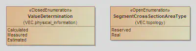
Enumerations are sets of predefined values. The VEC defines two concept for enumerations, Open and Closed enumerations (see Open and Closed Enumerations). You can find two examples in the figure below.
For the translation into RDF enumerations are treated as regular classes, in contrast to XML Schema, where an enumeration is just a xs:restriction on the xs:string datatype. To distinguish enumerations from regular VEC classes, the classes Enumeration, OpenEnumeration and ClosedEnumeration are explicitly defined in the ontology as follows (rdfs:comment and rdfs:label omitted).
vec:Enumeration rdf:type owl:Class .

vec:OpenEnumeration
        rdf:type         owl:Class;
        rdfs:subClassOf  vec:Enumeration .

vec:ClosedEnumeration
        rdf:type         owl:Class;
        rdfs:subClassOf  vec:Enumeration .

vec:enumLiteral
        rdf:type            owl:DatatypeProperty;
        rdfs:domain         vec:Enumeration;
        rdfs:range          xs:string;
        rdfs:subPropertyOf  rdfs:label .
The naming conventions for enumerations are the same as for regular classes. In addition, every Enumeration has a data property enumLiteral for the actual enum string value, as defined in the model. An enumeration in the UML model is translated to RDF as a subclass of OpenEnumeration or ClosedEnumeration. The Literals are translated as owl:NamedIndividuals of the class, the IRIs of the literals are created with the pattern: “<ClassName>_<LiteralName>”
vec:SegmentCrossSectionAreaType
        rdf:type         owl:Class;
        rdfs:subClassOf  vec:OpenEnumeration .

vec:SegmentCrossSectionAreaType_Reserved
        rdf:type         vec:SegmentCrossSectionAreaType , owl:NamedIndividiual;
        vec:enumLiteral  "Reserved" .

vec:SegmentCrossSectionAreaType_Real
        rdf:type         vec:SegmentCrossSectionAreaType , owl:NamedIndividiual;
        vec:enumLiteral  "Real" .
For OpenEnumerations the extension with new custom literals is straight forward. They can be easily defined as new individuals of the corresponding enum class. However, they should be defined in an appropriate namespace and not in VEC-namespace. The enumeration above could be extended for example like this:
acme:SegmentCrossSectionAreaType_MyCustomLiteral
        rdf:type         vec:SegmentCrossSectionAreaType , owl:NamedIndividiual;
        vec:enumLiteral  "MyCustomLiteral" .
In contrast to OpenEnumerations, ClosedEnumerations should not be extendable. Their set of enumeration values is predefined and closed. This semantic is expressed in the ontology representation by an equivalence axiom similar to the following:
vec:ValueDetermination
        rdf:type             owl:Class;
        rdfs:subClassOf      vec:ClosedEnumeration;
        owl:equivalentClass  [ rdf:type   owl:Class;
                               owl:oneOf  ( vec:ValueDetermination_Calculated vec:ValueDetermination_Measured vec:ValueDetermination_Estimated )
                             ] .
Primitives
The UML Model uses several primitive datatypes. The mapping to XML Schema datatypes, which are also used as primitive datatypes in RDF is the following:
String=xs:string
Double=xs:double
Integer=xs:integer
Int=xs:integer
Boolean=xs:boolean
Date=xs:dateTime
Associations & Attributes
Remarks about IRIs for Associations & Attributes
The VEC UML model identifies attributes and associations by their role name (compare figure VEC UML Model - Classes above), for example abbreviation in the class ItemVersion or referencedPart in the class DocumentVersion. Those role names are only unique within the defining class and not in the entire model.
There are cases where two classes in VEC model define an attribute with the same name and both attributes have in fact the same semantic (e.g. Identification or aliasId). However, there are also multiple locations, where the same name is used for different semantics (e.g. CurrentInformation is used in some context as information about the maximum current, and in another context as information about the regular operating currents).
The following approaches were considered for IRI generation for properties, but rejected after careful consideration:
- Opaque Names, like p1243 are a common approach to this problem. However, support of such an approach would have been a major extension to VECs the existing modelling infrastructure, switching between the classic XML-based World and RDF would be significantly more difficult and human readability data would be significantly more limited, which in turn might compromise the acceptance of the RDF representation.
- Using Property Names alone. This approach would have been fine, if all property names are unique within the model or have exactly the same semantic. However, as this is not the case, this blurring would result in various problems. Starting for example with simple things like properties with the same name have different data types. Defining
rdfs:domain/rangestatements on those properties would lead to inconsistencies or contradictions. - Qualifying ambiguous property names only. Translation rules would depend on the model history. If a unique property gets a new “twin” at some point, qualification would be necessary. However, the former unique property must retain its name for stability / backwards compatibility. This would lead to an incomprehensible situation as to why which property is fully qualified and when and which is not.
The following mapping rules apply for attributes & associations:
- In order to have a general, context free and simple translation rule, that creates stable and reproducible IRIs for properties, the IRI is always fully qualified. It is created with the pattern: “
<ClassName><RoleName>” where first letter of<ClassName>is lower case and the first letter of<RoleName>is upper case. - All primitive properties are mapped to
owl:DataProperty, all other properties are mapped toowl:ObjectProperty. rdfs:range/domainstatements are created, corresponding to the declaring class and the datatype of the property.- All properties that represent a “containment” are mapped as
rdfs:subPropertyOf vec:contains(explained further down). Containments are all attributes and all associations modelled as composite.
vec:itemVersionCompanyName
        rdf:type      owl:DatatypeProperty;
        rdfs:domain   vec:ItemVersion;
        rdfs:label    "companyName"@en;
        rdfs:range    xs:string .

vec:itemVersionAbbreviation
        rdf:type            owl:ObjectProperty;
        rdfs:domain         vec:ItemVersion;
        rdfs:label          "abbreviation"@en;
        rdfs:range          vec:LocalizedString;
        rdfs:subPropertyOf  vec:contains .
To map the hierarchical structure of the VEC, two general properties are defined as follows:
vec:contains
        rdf:type  owl:ObjectProperty;
        rdfs:comment  "This is the representation of the containment modeled in the UML. All associations that are a \"containment\" in the UML model are subproperties of this property."@en;
        rdfs:label    "contains"@en .

vec:parent
        rdf:type   owl:ObjectProperty;
        rdfs:comment   "The inverse of 'contains'."@en;
        rdfs:label     "parent"@en;
        owl:inverseOf  vec:contains .
Ordered & Non-Unique
The VEC model allows attributes & compositions to Ordered and associations to Ordered and/or Non-Unique. See the figure below for the different cases.
Side Note: Non-Uniqueness is only possible for associations.
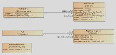
- Ordered means that the elements of the property / association have a specified order that has defined semantic in the domain. For example the order of the
TopologySegmentin aPathdefines the order in which a wire is routed through the topology. - Non-Unique means, that the same two element can be associated multiple times and that the number of associations is relevant.
Since RDF is a pure triple representation, there is no native way to represent order or non-uniqueness, in contrast to XML where all associations are ordered and non-unique per default. To represent these semantics in the VEC ontology additional model elements are introduced.
To express “order” as a general concept the class Ordered is defined as follows:
vec:Ordered
        rdf:type  owl:Class;
        rdfs:comment  "Class of elements that are ordered within their containment."@en;
        rdfs:label    "Ordered"@en .

vec:orderedIndex
        rdf:type  owl:DataProperty;
        rdfs:comment  "Defines the order of Ordered elements. Lower indices are further forward in a list. 0 is the lowest index, i.e. the first element."@en;
        rdfs:domain   vec:Ordered;
        rdfs:range    xs:nonNegativeInteger .
For all attributes & compositions order is defined within the context of the “container”. In consequence, there is only one order for each element, as there is only one container for each element. Therefore, the order can be “stored” in the element itself. In other words, all element that are contained in an ordered attribute or composition are also Ordered. In the ontology, this is expressed by the following triple:
vec:cavitySpecificationAngle
        rdf:type            owl:ObjectProperty;
        rdfs:domain         vec:CavitySpecification;
        rdfs:label          "angle"@en;
        rdfs:range          vec:NumericalValue , vec:Ordered;
        rdfs:subPropertyOf  vec:contains .
With associations, the same object can be referenced multiple times and receive different orders for each referencing.
For example, a segment can occur in different paths and in different places.
In these cases, a wrapper class is created in the ontology for the target class. The wrapper participates unambiguously in association in the context of the source object and references the actual target object.
This allows the non-unique semantics to be mapped. If ordering is also required, it is applied to the wrapper class, analogous to the mapping attributes and composition. For the Path / TopologySegment the resulting partial ontology is the following:
vec:pathSegment
        rdf:type   owl:ObjectProperty;
        rdfs:domain         vec:Path;
        rdfs:label          "segment"@en;
        rdfs:range          vec:TopologySegmentWrapper , vec:Ordered;
        rdfs:subPropertyOf  vec:contains .

vec:TopologySegmentWrapper
        rdf:type         owl:Class;
        rdfs:comment     "Container class for TopologySegment to participate in non-unique and/or ordered associations.".

vec:topologySegmentWrapperItem
        rdf:type      owl:ObjectProperty;
        rdfs:comment  "References the actual item for a Wrapper.";
        rdfs:domain   vec:TopologySegmentWrapper;
        rdfs:range    vec:TopologySegment .
UML to SHACL
In addition to the ontology, a SHACL schema is derived from the UML model to allow validation of RDF graphs similar to the classic XML schema.
Namespace
The namespace of the SHACL Shapes is http://www.prostep.org/ontologies/ecad/2024/03/vec-shacl# the recommended prefix is vecsh.
Classes
For each class a <ClassName>Shape is created, similar to the one listed below (shortened for readability). Constraints for cardinalities of associations and target types are generated.
vecsh:ItemVersionShape
        rdf:type         sh:NodeShape;
        rdfs:subClassOf  vecsh:ExtendableElementShape;
        sh:property      [ sh:class     vec:CopyrightInformation;
                           sh:maxCount  1;
                           sh:minCount  0;
                           sh:path      vec:itemVersionCopyrightInformation
                         ];
        #... more properties here ...
        sh:property      [ sh:datatype  xs:string;
                           sh:maxCount  1;
                           sh:minCount  1;
                           sh:path      vec:itemVersionCompanyName
                         ];
        sh:property      [ sh:class     vec:ChangeDescription;
                           sh:minCount  0;
                           sh:path      vec:itemVersionChangeDescription
                         ];
        sh:targetClass   vec:ItemVersion .
The constraints above ensure only the target types (objects) of the properties. Without additional constraints, a property could be used on any class as subject. To ensure that all properties are only used on the classes that declare the property in the UML model, for each class <ClassName>InverseShape is created, similar to the following one:
vecsh:ItemVersionInverseShape
        rdf:type             sh:NodeShape;
        rdfs:subClassOf      vecsh:ExtendableElementInverseShape;
        sh:class             vec:ItemVersion;
        sh:targetSubjectsOf  vec:itemVersionChangeDescription , vec:itemVersionCompanyName , vec:itemVersionCopyrightInformation
        #... more properties here ...
        .
Ordered / Non-Unique
For Ordered and Non-Unique attributes & associations the constraints are generated accordingly to the pattern described in the UML to OWL mapping section (see above).
vecsh:OrderedShape
        rdf:type  sh:NodeShape;
        sh:property     [ sh:datatype  xs:nonNegativeInteger;
                          sh:maxCount  1;
                          sh:minCount  1;
                          sh:path      vec:orderedIndex
                        ];
        sh:targetClass  vec:Ordered .

vecsh:PathShape
        rdf:type  sh:NodeShape;
        rdfs:subClassOf  vecsh:ExtendableElementShape;
        sh:property      [ sh:class     vec:Ordered , vec:TopologySegmentWrapper;
                           sh:minCount  0;
                           sh:path      vec:pathSegment
                         ];
        sh:targetClass   vec:Path .


vecsh:TopologySegmentWrapperShape
        rdf:type        sh:NodeShape;
        sh:property     [ sh:class     vec:TopologySegment;
                          sh:maxCount  1;
                          sh:minCount  1;
                          sh:path      vec:topologySegmentWrapperItem
                        ];
        sh:targetClass  vec:TopologySegmentWrapper .

vecsh:CavitySpecificationShape
        rdf:type         sh:NodeShape;
        rdfs:subClassOf  vecsh:SpecificationShape;
        sh:property      [ sh:class     vec:Ordered , vec:NumericalValue;
                           sh:maxCount  2;
                           sh:minCount  0;
                           sh:path      vec:cavitySpecificationAngle
                         ];
        #... more properties here ...
        sh:targetClass   vec:CavitySpecification .
Enumerations
A general EnumerationShape is create to ensure that all enumerations define a vec:enumLiteral.
For each enumerations an individual <ClassName>EnumShape is created to ensure that only defined literals are used.
For OpenEnumerations the sh:severity of such “violations” is lowered to sh:Info since the addition of new literals is explicitly allowed, but custom literals should reported nevertheless.
vecsh:EnumerationShape
        rdf:type        sh:NodeShape;
        sh:property     [ sh:datatype  xs:string;
                          sh:maxCount  1;
                          sh:minCount  1;
                          sh:path      vec:enumLiteral
                        ];
        sh:targetClass  vec:Enumeration .

vecsh:ValueDeterminationEnumShape
        rdf:type        sh:NodeShape;
        sh:in           ( vec:ValueDetermination_Calculated vec:ValueDetermination_Measured vec:ValueDetermination_Estimated );
        sh:targetClass  vec:ValueDetermination .

vecsh:SegmentCrossSectionAreaTypeEnumShape
        rdf:type        sh:NodeShape;
        sh:in           ( vec:SegmentCrossSectionAreaType_Reserved vec:SegmentCrossSectionAreaType_Real );
        sh:severity     sh:Info;
        sh:targetClass  vec:SegmentCrossSectionAreaType .
Handling of Identifiers
The VEC and its XML Schema offer different concepts for the identification of model elements addressing certain requirements and those shall be used accordingly.
Identification-Properties (VEC Model)
Many types defined in the VEC model have an “Identification” property (e.g. the OccurrenceOrUsage).
This is meant to be a semantic identifier of the object represented by the VEC element. The following rules apply to those identifiers:
- The expectations defined in the documentation of the VEC model of the corresponding attribute shall be ensured.
- The identifications shall be unique for a certain element type, at least within its context element. In other words, the VEC model and its representation as XML Schema is a hierarchical data model. That means, that an identification shall be at least unique within its direct parent element (e.g. the identification of a HousingComponent shall be unique within its EEComponentSpecification.
- Two elements of different types can have the same Identification. However, this is only recommended, when the two VEC elements represent the same domain entity from different points of view, otherwise this shall be avoided as far as possible.
- In general, it is recommended to keep the Identifications stable over the time. This means, that if an object is exported multiple times the Identification of it should be the same. However, this is not possible in all cases, for all processes and all tools. Therefore, a process and / or tool creating VEC files should describe for all elements, under which conditions Identifications are stable or new ones are created.
AliasIdentification-Properties (VEC Model)
Certain elements have the capability to define AliasIdentifications in addition to their
unique identifications. AliasIdentifications are scoped identifiers of the object. The scope can be a system, a company
or or process. One use case of this kind of ids is the creation of traceability links between different sources of information. Examples for usages of the AliasIdentifications are:
- The identifier of a connector in the electrological process (with geometric variants)
- The identifier of a node or segment in a MCAD tool
- An assigned UUID of an element.
id-Attributes (XML Representation)
All xs:complexType define an id-Attribute with the type xs:ID. These are technical ids
that are necessary for the referencing mechanism of the VEC within a single XML file.
The semantics, constraints and requirements are defined by the XML Standard and
XML Schema itself. These ids do not have any significance outside a VEC file.
See the Section id-Attibutes.
immutable-global-id-Attributes (XML Repesentation)
See the Section immutable-global-id-Attributes.
IRIs (RDF Representation)
In RDF all objects (named resources in RDF) require a global unique identifiers which is an IRI. This is mandatory for resource to be “referencable”.
The maturity of the IRI generation strategy decides quality & stability of links within RDF graphs. There it should be thoroughly thought through when representing VEC data in RDF.
The RDF IRI is very similiar to the immutable-global-id feature in VEC XML representations. When mapping VEC data from XML to RDF and back, it should be possible to use immutable-global-id (when defined), as RDF IRI and vice versa.
However, RDF IRIs are a standard concept defined in RDF, whereas the immutable-global-id are a specific feature of the VEC XML representation.
Extension Rules
If the well-defined data structures and fields are not sufficient for the specific needs of a process or a tool, the VEC provides powerful extension mechanisms. Namely the extension mechanisms are custom properties and open enumerations (see the corresponding chapters in the model description).
However, it should be considered that information transported via these mechanisms is not standardized and is always subject to an individual agreement between interface partners. Therefore, these mechanisms shall be used with extreme caution.
It is strictly forbidden to use these mechanisms for the transfer of information that is already standardized within the VEC. In particular it is not permitted:
- To store information in custom properties where already well-defined concepts exist in the VEC to store the same information, e.g. using a custom property instead of an attribute or a more specific class in inheritance tree.
- To use self-defined OpenEnumeration-literals when well-defined literals with the same semantics already exist.
VEC-Files that do not obey to these rules are noncompliant to this data format specification.
If the extension mechanisms are used, it shall always be considered if these extensions might be a valid feature request for the VEC Standard.
Type Inheritance
The VEC uses an object-oriented class and inheritance concept. The following clarifications apply to its use:
- Only non-abstract classes can be instantiated.
- In an inheritance hierarchy, the choice of the used type represents a semantic
information itself. For example, the usage of a
PluggableTerminalSpecificationis a more specific information than the usage of aTerminalSpecification. It is not required to use the more specific class if the information is not available or it should not be transmitted. However, it is not permitted to use the more general class and transfer the information of the more specific class in a custom property, or similar (e.g. use theTerminalSpecificationwith aCustomPropertytype=pluggable).
Default- and Missing-Value Handling
For various reasons, there may be attributes of entities where no value can be exported, or a special semantics is required. The cases are:
- The information is not supported by the system / process. So, it is never available for this system / process.
- The information is supported by the system; however, the value is not defined by the user.
- The information is explicitly defined as “arbitrary” for the use case (e.g. the part version in a bill of material or a compatibility statement).
All cases might exist for mandatory attributes as well as for optional attributes. Due to
the design, numerical values in the VEC and its high level of optionality the following
definition of special values should be only relevant for xs:string-Attributes:
| Mandatory Attribute | Optional Attribute | |
|---|---|---|
| Unsupported | <tag>/NULL</tag> | omitted tag |
| Undefined | <tag></tag> | <tag></tag> |
| Arbitrary | <tag>/ANY</tag> | <tag>/ANY</tag> |
/NULL&/ANYmeans, that the attributes with the name “tag” in the VEC receive these values.<tag></tag>means, that an attribute with the name “tag” and an undefined value is represented in the VEC as an existing XML element with no value (no contained text() node).omitted tag: means the element tag for the attribute is not present in the VEC
xs:double has less flexibility of allowed values. If the equivalent of /NULL is required for xs:double valued attributes, NaN shall be used. The other cases for xs:string-Attributes, mentioned above, are not supported by xs:double-Attributes.Instantiation of Model Structures
There are various locations in the VEC model where structures / patterns are defined
and used / instantiated somewhere else (e.g. a connector with its slots and cavities).
In most cases, the elements in the definition of a structure have corresponding
elements in the instancing (e.g. ConnectorHousingSpecification →
ConnectorHousingRole, Slot → SlotReference & Cavity → CavityReference).
In cases where defined structures are instantiated, these structures shall be
instantiated completely. That means, for every element in the structural definition a
corresponding element in the instancing shall exist, regardless if it is used in the
respective VEC or not (e.g. for each Cavity of a ConnectorHousingSpecification, a
CavityReference in the corresponding ConnectorHousingRole shall exist). This applies
to the following list of structures, which is here for reasons of clarification and which is
not exhaustive:
- Connectors
- Wires
- EEComponents
- CompositeParts (e.g. Assemblies or Modules)
Expected Behaviour of VEC Interfaces
A wide range of different systems, supporting different use cases, are used in the process of wiring harness development. All of them might have a VEC-Interface for input & output, so sooner or later the question arises “What are the expectations for the behavior of those interfaces?”. This section will discuss this question.
Background
In a document based data exchange scenario (e.g. working with a word processor) the intuitive expectation is, that a document / file is “opened”, changes are performed and the document is “saved” again, with the document now containing the original content plus the modifications.
However, this simple and intuitive approach is not feasible in a model based data exchange scenario like the one for the VEC. The VEC is not intended to be a file-based database that contains all information about a vehicle network, which grows continuously over the time (like a Word document or an ODT file of a book). The basic idea of the VEC is, to provide a consistent language (model) for data exchange in the process of wiring harness development and to allow the exchange of use case specific slices of information within the process between systems and organizations.
This fundamental concept means that there is no such thing as “the one VEC interface”. The important question is, which use cases (or slices) of the VEC data model are supported or required for a specific interface.
Let’s assume that in our system landscape one component is responsible for the synthesis of electrology and geometry, and the derivation of a wiring harness from it. Such a system would potentially have 4 interfaces requiring different sections of the VEC model:
- Topology (IN)
- System or Wiring Schematic (IN)
- Part Master / Component Data (IN)
- Harness Definition (OUT)
In addition, the scope and validity of the different information slices may vary. For example, component data could be updated daily, with only the changed components at a time, but with a global validity, while a wiring harness definition is only valid for a specific vehicle context.
Even when considering only this example, it is already obvious that it does not make any sense to formulate requirements on cross-relationships between imported and generated VEC data, like “a system has to be able write all VEC data it has imported in an unchanged matter”.
Content of a VEC
A VEC can contain any scope, amount and combination of information that is valid, with respect to the VEC Model and the Implementation Guidelines. There shall be no requirement to create VECs with restricted content specifically for importing / receiving systems.
A receiving system shall be able to accept any valid VEC. If the VEC contains more than the required information of the system, the system is free to ignore the pieces of information irrelevant for its purpose. It does not have to store the ignored pieces for a later reexport. However, it shall not refuse the import of a VEC because of “too much” information.
On the other hand, it is up to the system to verify that a VEC contains enough information for the use case of the system. If that is not the case, the system can reject the import because of “too little” information.
Traceability Scenarios
Even though it is not possible to define general relationship requirements between imported and exported data, there are use cases in which a traceability between imported and exported data is required. In such cases, slices of imported data might be embedded into the exported data. This scenario is described in section “Combination and Reuse of Documents”
Summary of the Requirements
The aforementioned results in the following general requirements for systems with VEC interface:
- A system is not required to interpret, implement or store the full extent of the VEC model, when only portion of it is required for its specific use case.
- A system must be able to extract the information relevant for its use case from VEC files that contain more information than the system itself requires or is able to process.
- A system is only required to export the information relevant to its use case. In other word, in a roundtrip scenario with a “more powerful” system it may return less than it has received.
- On the other side, a system that is able to export a very extensive VEC is not required to strip the information down for a “less powerful” system.
- A system can reject VEC files that do not contain enough or only irrelevant information for its use case.
Key Concepts
External References
For reasons of traceability (e.g. requirements) or because certain information is better represented in other standards than in the VEC format (e.g. 3D models for components), it is necessary to be able to reference external documents from VEC elements. This guideline describes how these external documents can be addressed and what concepts exist to connect those documents with VEC model elements (and when to use which).
Referencing an external Document
As described in the Implementation Guideline “General Structure” the DocumentVersion serves several purposes, one of which is the referencing of external Documents. So, whenever a connection between a VEC element and an external document should be created, a DocumentVersion is required to address the document. Such a DocumentVersion should contain no payload data (Specification). However, it contains the same meta-data as it would, when included as a full featured document (e.g. DocumentType).
index.vec file consists practically only of such external references, as described in the recommendation Chapter “VEC-Packgage” and in the corresponding Implementation Guideline.There are different possibilities to resolve such a reference and retrieve the actual document:
- PDM reference with Domain Key: Per definition, a document version is unambiguously identified with its DocumentNumber, DocumentVersion and CompanyName. With context knowledge about the process, the document can be resolved in the corresponding PDM / Document Management System.
- FileName: If the document is packaged together with VEC file (VEC Package) the filename attribute of
DocumentVersioncan point to a location within the VEC Package. If the document is not part of the VEC Package, the FileName-Attribute shall be omitted. - Location: If the document can be resolved outside the VEC package, the Location-Attribute can point to a location (via an URN or URL) where the document can be resolved. For files that are stored following a specific procedure or systematics (e.g. in PDM System) the usage of URNs should be the preferred way. This decouples the referencing from a concrete physical location, which might be different in different contexts or might be changed over the time.
Connecting VEC Model Elements
After defining an external reference as DocumentVersion there are multiple approaches to create connections to VEC model elements. Some approaches have a specific semantic, some are more generic. The different possibilities are summarized below. If there are more than one possibility for a specific element, you have to choose the one with most specific semantics.
DocumentVersion.ReferencedPart →PartVersion: The document describes the part in some way (e.g. a component drawing). See “Parts, Documents and Resources”.DocumentVersion.RelatedDocument: The association is an informative link which DocumentVersion are related to each other (e.g. by derivation, A Harness-Drawing is related to a 3D-Model). See “Parts, Documents and Resources”.RequirementsConformanceStatement.DocumentVersion: SomePartVersions are satisfying (or not) the requirements defined in the external document. See “Conformance to Requirements”.ExternalMappingSpecification.MappedDocument: The external document is a different view on the same content described by this specific VEC and a mapping / active linking between the same elements in both views should be created. For example a harness and its drawing in SVG. See “External Mapping”.DocumentBasedInstruction.ReferencedDocument: AnOccurrenceOrUsagehas specific installation instructions that are defined in an external document (e.g. a manual or a working specification). See “Installation Instructions”.ExtendableElement.ReferencedExternalDocuments: The referenced document contains additional information about the VEC element, that cannot be represented in the VEC in an appropriate way. See “Parts, Documents and Resources”.DocumentRelatedAssignmentGroup.RelatedDocumentVersion: ADocumentRelatedAssignmentGroupallows the creation of traceability links to elements in aDocumentVersionfor a set of VEC objects. The semantic of the traceability link is defined by theDocumentRelationType, for example requirements that apply to these VEC elements. See “Assignment Group”.
External Mapping
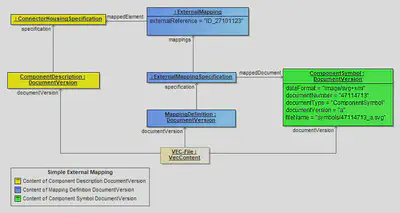
The diagram above shows the usage of the external mapping mechanism. The elements highlighted in yellow represent the actual information described by this VEC instance. The elements highlighted in blue are defining the mapping itself and the DocumentVersion highlighted in green represents the link to the mapped document (in this case a SVG-symbol).
The ExternalMapping in this example defines that a representation of the referenced ConnectorHousingSpecification can be found in the SVG-symbol under the key ID_27101123. This is especially useful, if one wants address specific subelements (e.g. for highlighting). In the example, the Cavitys of the connector could also be mapped to specific symbols within the SVG.
The actual content data of the VEC-file (highlighted in yellow) and the mapping information is separated into two different DocumentVersion elements. This means even though both information are contained in the same VEC-file, from the perspective of a versioning mechanism they are clearly separated.
External Installation Instructions

The usage of file-based installation instructions is quite similar to the described approach for external documents. The FileBasedInstruction defines a pointer to the file packaged together with the VEC-file in the container and is referenced by the PartOccurrence.
The same effect could be achieved if a DocumentBasedInstruction is used, pointing to an external document (defined as described in the section before).
Important: The difference between the two approaches is that for the DocumentBasedInstruction a DocumentVersion is required. This means that the external file must be an official document with a document number, an appropriate versioning and so on. The FileBasedInstruction can point to any file needed (within a VEC package).
It is forbidden to use the FileBasedInstruction approach, if the external file is a valid document.
General Structure of VEC Files & Documents
The VEC has two major key concepts: PartVersion and
DocumentVersion. Both are ItemVersions and
both are used to reference / identify a piece of relevant information in a PDM
context unambigiously.
Whereas the PartVersion “just” represents a PDM anchor /
reference for a part or component plus some Meta-Information, the
DocumentVersion has different characters in the VEC (for more
details see section Usages of the
DocumentVersion):
- It can serve as a plain PDM anchor / reference to a document, with no further
content / information in the VEC, like the
PartVersionfor parts (VEC equivalent to the KBL External_reference). - However, more important is that the
DocumentVersionis the container for any payload information contained in the VEC.
From a meta data perspective, the VEC does not differentiate between documents that are contained in the VEC itself or in some external place somewhere else. This guideline is intended to provide guidance on how these concepts should be used and how an appropriate distribution of documents can look alike.
Fundamentals
On the root level, a VEC contains mainly PartVersions and
DocumentVersions and some other unversioned (and constant)
information, e.g. the definition of the Units used within the
VEC. This is illustrated in figure Basic
Structure.

One of the core concepts of the VEC is, that there is no restriction for the
type of information that can be contained in a DocumentVersion
nor the valid combinations of different types of information that can be
contained together. This enables the DocumentVersion to
reflect the actual circumstances of the domain or process and thus represents an
actual technical document with a corresponding release and versioning.
Reasonable combinations of information are driven by the use cases (with process specific variations). The description of some common use case is part of this guideline.
A document can contain any number of Specifications. The
Specifications represent the information modules of the VEC
and each defines a certain type or aspect of information. The
Specifications in a document can be thought of like drawers,
where each drawer contains a specific aspect of the vehicle network. A
distinction can be made here between:
- General specifications, that are for example required for the provision of
basic information or for information reuse (e.g. an
InsulationSpecification), and PartOrUsageRelatedSpecifications that are specifically used to describe / specify the properties of one or manyPartVersions.
Parts and Documents
One of the most fundamental concepts of the VEC is the separation of a part /
component from its definition (specification). In this, the
PartOrUsageRelatedSpecification plays a major role.
In the VEC a part (PartVersion) does not contain any information
about the part, except its PDM Information (PartNumber, PartVersion, …). All
the information about the technical properties of a part is expressed by a
subclass of PartOrUsageRelatedSpecifications (e.g. a
WireSpecification). The
PartOrUsageRelatedSpecification is contained in a
DocumentVersion. As mentioned above, the distribution of these
specifications into different documents is driven by the process / domain (see
object diagram Parts and
Documents).
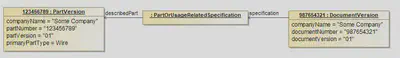
This approach enables the VEC to address for example the following scenarios properly:
- The description of a part is changed, but the part itself is not changed
(rereleased). This can happen for example if the actual technical properties
of the part stay the same, but the description is extended or corrected. In
this case, a new version of the document is created. However, the
PartVersionstays the same. - A document and the contained specifications are describing more than one part (e.g. a drawing for a certain class/family of terminals, seals & plugs). In this case it can happen that the document and the specifications are changed, but not all of the described parts have to be changed (rereleased). E
Usages of the DocumentVersion
As mentioned in the introduction, the DocumentVersions VEC can
be used in different ways:
- Plain PDM reference (a.k.a as external reference): In this case, the
DocumentVersionin the VEC only contains meta-data and no payload-data (noSpecifications). This is described in detail here. - Digital Representation of an external Document: There are use cases where
existing documents can represented in the means of the VEC. In other words the
VEC
DocumentVersionis a digital representation of the original document. For example, the information of a component data sheet (as PDF) might be also represented in VEC in a digitally evaluable way (PartOrUsageRelatedSpecification). In this case the same mechanisms like for the plain PDM reference can be used, plus payload-data inDocumentVersion. - Native VEC Documents: The VEC
DocumentVersionitself is the source of information. This case is quite similar to the digital representation scenario. However, external links (if defined) will resolve to the VEC file itself.
However, regardless of the use of the DocumentVersion, it always represents the meta-data of the entity in the process, which does not change depending on its VEC representation. Meaning, if for example a system schematic is referenced as external document in one place (VEC file) and is used as a native document / digital representation in another place, it is still a system schematic (DocumentType) with the same DocumentNumber & Version.
Combination and Reuse of Documents

Typically, information is flowing through the process. It is created somewhere,
passed on to someone else and is used there to create other information blocks.
To make these information flows traceable each piece of information must be
identifiable and must have a change indicator. In the VEC this is done by the
DocumentVersion. In order to preserve this traceability along
the process, the assignment of information pieces to its original
DocumentVersion shall remain unchanged.
An illustrative example for this, is the distribution and use of component
master data (compare figure on the
right). As
described in XML / XSD Representation
component master data is best provided with one VEC per component, containing at
least one DocumentVersion with the component’s specifications
(VEC A, B, C).
If a wiring harness is created with these components, the component master data
(at least a portion of it) is required in the data set of the harness (VEC
NEW). However, the information is not integrated into the
DocumentVersion of the harness (DocumentVersion NEW), as
this would lead to a loss of traceability, even if the structures of the VEC
would allow such an approach. Instead, copies of the
DocumentVersions containing the component’s part master data
are placed beside the DocumentVersion of the harness, within the same VEC.
A DocumentVersion in the VEC and the physical VEC file shall not be equated. A DocumentVersion is a logical entity and can be contained in multiple VEC (files). Conversely, a VEC file can contain multiple DocumentVersions.
Even though the logical content (the represented object graph) of a self contained
DocumentVersion might be copied from one VEC file to another without problem,
the actual XML snippet might require adaption. At least the XML ID-attributes must
be checked for uniqueness and, in case of a conflict, changed. Referencing IDREF(S)
also have to be changed accordingly.
Content from mixed Sources
Disclaimer: This page or section is currently under review by the community.
The content of this page or section can be subject to change at any time. If you find any issues or if you have any review comments please drop us an issue in our Issue Management on GitHub.
This page or section resolves #956
It is a common scenario that a VEC model contains information from different sources. In some cases it is pretty obvious that the information comes from different sources, e.g. part master data from a component database, a system schematic from an ECAD tool, and a geometry model from a 3D CAD system.
However, there are also use cases where the information from different sources is not so clearly distinguishable by its type. It is even possible, that the same type of information is obtained from different sources. Some examples for such scenarios are:
- Occurrences of components are defined in different places / process steps, e.g. in the electrologic, DMU or in the actual harness design.
- Additional information like placements and routing might come from different tools or process steps as well.
There are two apporoaches to handle such scenarios in the VEC, while keeping the traceability of the information to its source:
- Separate DocumentVersions per Source: In this approach, the information from each source is contained in a separate
DocumentVersion. This is the preferred approach, as it clearly separates the information from different sources and preserves traceability in the change management. EachDocumentVersioncan be clearly associated with its source, e.g. by using appropriate meta-data like document type, document number, version, etc. - Single DocumentVersion with individual Specifications: This is approach is used, if all information must be combined into a single
DocumentVersion. The information from different sources is kept separated by using individualSpecifications for each source. However, this approach lacks the clear representation of source metadata on theDocumentVersionlevel (e.g. document number & version), which might impact traceability for example in the change management.
Types of Documents
The DocumentType is an OpenEnumeration that
defines some document types that are common in the harness development process.
The following sections describe typical content that can be expected in the
DocumentVersions of a specific type, if the content is represented in the VEC.
However, as the DocumentVersion is primary an entity from the
domain of the creating process, the content and the given
Specifications may vary.
Part Master
A part master document describes the properties of a component or a group of
components (a PartVersion or a set of
PartVersion). It contains some general purpose specifications
that provide information for any component type. A detailed description can be
found in the “Component Description”
Guideline.
Master Data Definition
In contrast to PartMaster documents MasterDataDefintions are not related to a specific component or a set of components (equivalent to part, part number, etc.). MasterDataDefintions are predefined standard information pieces in the process declared by some central organizational unit.
It is a common approach to manage certain information centrally and distribute it in the development processes. The definition of this information is usually independent of specific development projects and ensures the adherence to certain conventions and guidelines across (all) development projects. The component master data is a very specific aspect of this information as it always refers to a component (with a part number). In addition, there is a wide range of other information that is not directly related to a specific component but is nevertheless managed centrally.
Such DocumentVersions with central definition, that are not
related to specific PartVersion are summarized under the
DocumentType MasterDataDefinition. Examples for such
centrally distributed informations are:
- Usage Node Lists (
UsageNodeSpecification), - Signal Catalogs (
SignalSpecification), or - Standardized Base Specifications (e.g.
CavitySpecification,InsulationSpecification)
Extension of Master Data Definitions

A VEC that requires master data definitions of a specific type (e.g. signals, usage nodes) can obtain these from different sources (e.g. seperate signal catalogues for power & information). A special use case of this is the addition / extension of a master data definition with individual information in a specific development artifact.
Example: New signals might be required in the system schematic of a new series that are not (yet) included in the master data definition. These additions could be contained in a local signal catalog of system schematic, while the central master data catalog is used for the other signals. When the development process has progressed, these local definitions might be included in the master data definition.
The following bulletins illustrate some examples of different, process specific consistency relationships. The examples are from the context of the above mentioned “signal catalogues”.
- Different Sources for separate domains (e.g. power signals vs. information signals): In this case, there should be no overlaps between the defined entities.
- Local / project specific definitions vs. global definitions: In this case it depends on the degree of freedom allow for project specific definition. Or, viewed from the other direction, on the binding nature of the global definitions. This determines whether only new information may be added or whether existing elements may be overwritten with other information.
In any case, the order of precedence has to be defined for the different sources. However, this is mainly an issue for the business logic of an authoring use case (which elements can be defined or selected by the user in a certain context). In the data exchange use of the VEC, the elements from the different sources are explicitly referenced. So at any time it is unambiguously defined which elements have been used / selected, even though the rules why an element took precedence over another are not contained in the VEC (compare figure Master Data Extension)
Change Tracking of Document Versions
As described in detail in the Implementation Guideline “General Structure / Usages of the DocumentVersion” one use case of the DocumentVersion is to serve as a payload data container within the VEC, either for the digital representation of an external document or for native digital data. This Implementation Guide is about the possibilities to track changes and modifications of this payload data within the VEC. Be sure to read Parts, Documents and Resources before, as it also contains important information about this topic.
In the VEC, data is organized in DocumentVersions and those are unambiguously identified by CompanyName, DocumentNumber and Version. Those attributes are identifying an entity relevant for the process as the single source of truth for this information, for example a drawing, a data sheet or even an entity in a database. The handling of those attributes and the corresponding change procedures are driven by the process and not by technical requirements. In many cases the VEC only contains a digitally readable representation (an export) of that information.
Consequently, the identifying attributes and in particular the Version are only changed, when the relevant process entity has changed, according to rules applied by the process (e.g. a new version of a drawing has been created and approved). However, there are numerous scenarios (described in detail below) where the payload content in a VEC DocumentVersion can change, without a change of the underlying process entity. To allow the content of a DocumentVersion to be marked as changed in such scenarios, the DigitalRepresentationIndex was introduced. If the DigitalRepresentationIndex has changed, the content of the DocumentVersion must be checked for changes, otherwise the content can be assumed unchanged (see Parts, Documents and Resources for a definition of “unchanged”).
Application of the DigitalRepresentationIndex
When to Use
The DigitalRepresentationIndex is an optional feature of the VEC that softens the requirements for the change semantic of CompanyName, DocumentNumber and Version in cases where the content of a DocumentVersion in the VEC changes, without being able to at least adjust / increment the Version-attribute.
When to Modify
A reading system can assume the payload content of a DocumentVersion unchanged, when the DigitalRepresentationIndex has not changed between two VEC files. The DigitalRepresentationIndex shall be different, whenever the payload content of a DocumentVersion with the same CompanyName, DocumentNumber and Version is different. If a clear statement is not possible, a change is to be assumed in case of doubt.
As mentioned before, there are multiple scenarios where such a situation might occur. The illustration below is intended to explain some examples of such scenarios.

In all scenarios, the content of the DocumentVersion in a VEC files might be different, resulting in a modified digital representation index, for the same (unchanged) source document. For the example, assume the document entity in the process is an approved component drawing as PDF (highlighted in blue on the left hand side of the figure). This is the document identified by CompanyName, DocumentNumber and Version. The following situations might occur that result in different digital representations without changed source document:
- In a first step (marked with (1)), the information from the drawing is transferred manually into an IT-System (e.g. a component database). A first digital representation is created. However, this representation might be changed at a later point for multiple reasons:
- A mistake / typo occurred during the manual data transfer and is corrected.
- Data management guidelines or the underlying IT-System changed and more information from the original document has to be transferred.
- This data is exported into a Component Data VEC (marked with (2)). If this is done multiple times, different digital representation might be created due to:
- Added features of the exporter resulting in more information in the export.
- A bug fix for the exporter component or the exporting system.
- An update of the underlying VEC version.
- The component data is used to create other artifacts in the development process (marked with (4)). For this, at least parts of the original information might be embedded in the new artifact for traceability reasons. Another digital representation is created.
- A system might provide different export flavours with different content levels depending on the recipient. For example a VEC for external partners might contain less information as a VEC for internal use.
- The source document might contain various information. E.g. a single component drawing can define a complete family of components (e.g. a family of terminals). When creating a VEC file per component (recommended approach for a component database), the resulting VEC file should only contain the information relevant to exported component and not all components defined in the drawing. Therefore, you might have different
DocumentVersions containing different information slices of the same source document (illustrated in the figure below).

An indication of change with DigitalRepresentationIndex is mandatory only if the payload data content of a DocumentVersion has changed (e.g. changed, added or removed attributes or contained objects). It does not require that the resulting XML serialization is binary identical.
Changes related to the technical aspects of XML representation do not require a DigitalRepresentationIndex. This includes, but is not limited to changes of XML ID & IDREF elements (assuming the referenced objects are the same), ordering of XML elements and XML Meta elements like XML Comments ("<!-- ... -->") or XML Processing Instruction (<?target instructions?>)
How to Create
The VEC does not define any specifications for the construction of the DigitalRepresentationIndex (e.g. syntax, order). The only requirement is, that two values can be checked of equality. If the values are equal, the payload data can be assumed unchanged, if the values are different, the payload data might be different as well.
It is up to the discretion and capabilities of the generating system to define a suitable and possible algorithm to generate the index. However, it should always be taken into account that an unnecessary change indication creates needless overhead on the side of the reading systems.
Possible approaches include:
- An internal change tracking index of the creating system (e.g. revision number)
- A checksum created over the relevant payload data
- A timestamp, either of the last change in the creating system or the time of the VEC creation.
- A UUID identifying a specific digital representation. Each time a new digital representation is created a new UUID is generated.
Usage Nodes

The example illustrates the use of UsageNodes. A UsageNode represents a position in an abstract vehicle. For example the Head Light Left. UsageNodes belong to the master data and they are defined on some company wide level. They can be used to enforce consistent naming over different projects and different development streams (e.g. between geometry and electrologic).
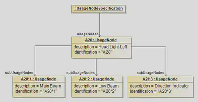
A UsageNode can be subdivided into more detailed UsageNodes. For example the Head Light can be split up into Main Beam, Low Beam and Direction Indicator.
The diagram above shows this usage of sub usage nodes. There is one main usage node “A20” with it’s sub nodes “A20*1”, “A20*2” and “A20*3”. For simplification of the following code snippet only the XML representation of the definition of the parent usage node “A20” and its child node “A20*1” is shown.
<Specification xsi:type="vec:UsageNodeSpecification" id="id_usage_node_spec_1">
  <Identification>UsageNodeList</Identification>
  <UsageNodes id="id_usage_node_1">
    <Identification>A20</Identification>
    <Description xsi:type="vec:LocalizedString" id="id_1">
      <LanguageCode>En</LanguageCode>
      <Value>Head Ligth left</Value>
    </Description>
    <SubUsageNodes>id_usage_node_2</SubUsageNodes>
  </UsageNodes>
  <UsageNodes id="id_usage_node_2">
    <Identification>A20*1</Identification>
    <Description xsi:type="vec:LocalizedString" id="id_2">
      <LanguageCode>En</LanguageCode>
      <Value>Main Beam</Value>
    </Description>
  </UsageNodes>
[...]
</Specification>
Physical Properties
Numerical Values
Many technical properties are defined as NumericalValue. Those consist of a numerical value in a defined Unit and an optional Tolerance.
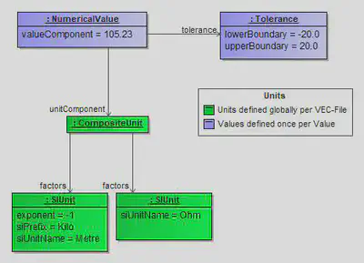
The object diagram above illustrates the VEC representation of the following value:
$$105.23 \ \Omega /km \pm 20.0$$
Units
Units that are used within a VEC are defined globally within the VEC file (under the VecContent) and reused / referenced by each NumericalValue. The VEC allows a wide variety of different Units from different systems of units. The following XML snippet contains some concrete examples for Units. The first three units (id_unit_1, id_unit_2 & id_unit_3) in the snippet are the XML representation of the example above.
<vec:VecContent ...>
    [...]
    <Unit xsi:type="vec:SIUnit" id="id_unit_1">
        <SiUnitName>Ohm</SiUnitName>
    </Unit>
    <Unit xsi:type="vec:SIUnit" id="id_unit_2">
        <Exponent>-1</Exponent>
        <SiUnitName>Metre</SiUnitName>
        <SiPrefix>Kilo</SiPrefix>
    </Unit>
    <Unit xsi:type="vec:CompositeUnit" id="id_unit_3">
        <Factors>id_unit_1 id_unit_2</Factors>
    </Unit>
    <Unit xsi:type="vec:SIUnit" id="id_unit_6000">
        <Exponent>2</Exponent>
        <SiUnitName>Metre</SiUnitName>
        <SiPrefix>Milli</SiPrefix>
    </Unit>
    <Unit xsi:type="vec:SIUnit" id="id_unit_170">
        <SiUnitName>Gram</SiUnitName>
    </Unit>
    <Unit xsi:type="vec:SIUnit" id="id_unit_442">
        <SiUnitName>DegreeCelsius</SiUnitName>
    </Unit>
    <Unit xsi:type="vec:SIUnit" id="id_unit_189">
        <SiUnitName>Ampere</SiUnitName>
    </Unit>
    <Unit xsi:type="vec:SIUnit" id="id_unit_445">
        <SiUnitName>Volt</SiUnitName>
    </Unit>
    <Unit xsi:type="vec:SIUnit" id="id_unit_196">
        <SiUnitName>Second</SiUnitName>
    </Unit>
     [...]
</vec:VecContent>
Reference Systems
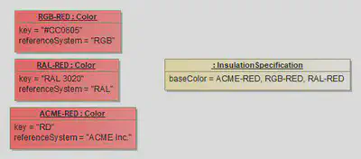
This tutorial demonstrates how values with reference systems shall be used. In many cases (e.g. Colors) there is no single correct way to express a certain literal, but many different ways.
In order to correctly express such values, the VEC gives the possibility to define not only the value, but also the reference system in which the value is defined. This means if there have three valid ways to express the Color “Red”, the VEC allows to define and differentiate all of them. If the value is defined in some standard reference system this ca be used (e.g. RGB or RAL for colors). If the value is defined in some company specific reference system, this can be defined, too (see ACME Inc.). For attributes like the “baseColor” of a wire insulation it is possible to define the single value in the representation different reference systems (in the example the color RED in RGB, RAL and a company specific “ACME Inc.” system). However all given representations shall refer to the same “real” value.
The example shown in the figure Reference Systems has the following XML representation:
<vec:VecContent ...>
    [...]
    <DocumentVersion id="id_1">
        [...]
        <Specification xsi:type="vec:InsulationSpecification" id="id_2">
            <Identification>...</Identification>
            <BaseColor id="id_3">
                <Key>#CC0605</Key>
                <ReferenceSystem>RGB</ReferenceSystem>
            </BaseColor>
            <BaseColor id="id_4">
                <Key>3020</Key>
                <ReferenceSystem>RAL</ReferenceSystem>
            </BaseColor>
            <BaseColor id="id_5">
                <Key>RD</Key>
                <ReferenceSystem>ACME Inc.</ReferenceSystem>
            </BaseColor>
        </Specification>
    </DocumentVersion>
    [...]
</vec:VecContent>
Custom Properties
This implementation guideline gives more details and examples on the usage and the correct interpretation of the VEC concept: Extensibility with Custom Properties.
CustomProperty is available in all subclasses of ExtendableElement. In the following examples the class Person is used, which intentionally is not a subclass of ExtendableElement, but for a clear and easy to understand example of custom properties it is well suited.
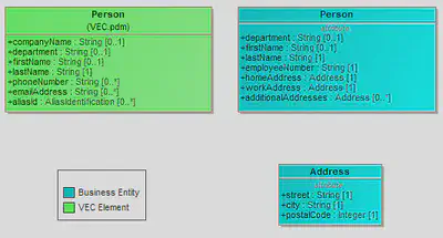
The left side shows the Person class as defined in the VEC. The right hand side shows an excerpt from the domain of an arbitrary Tool. As you can see in the UML model, the class on the right side contains the attributes employeeNumber and different usages of the class Address, which are both not represented in the VEC. Despite the lack of explicit modelling concepts with this specific semantic, the extension mechanisms of the VEC still allow the exchange of this information within the VEC. The VEC supports extensions of the following type:
- Additional properties (attributes), either single or multi-valued (All subclasses of
CustomProperty, e.g.SimpleValuePropertyorBooleanValueProperty). - Contained structures, either single or multi-valued (the
ComplexProperty, e.g. simple objects like the address).
These concepts do not support the extension of elements with additional relationships (IDREF in XML).
XML Examples / Snippets
The following XML snippets illustrate the correct usage of the concepts to support the business model shown in the UML diagram above.
Simple Property
The snippet shows the extension of a Person object by the property EmployeeNumber (String). The VEC supports a wide range of primitive property types (e.g. Boolean, Date, Numerical, see the subclasses of CustomProperty for a complete list), so keep in mind to choose the correct type for the corresponding value.
<vec:VecContent ...>
    [...]
    <Person id = "id_01">
      <CustomProperty id="id_01_1" xsi:type="vec:SimpleValueProperty">
          <PropertyType>EmployeeNumber</PropertyType>
          <Value>ABC123</Value>
      </CustomProperty>
      <Department>IT</department>
      <FirstName>John</firstName>
      <LastName>Doe</lastName>
    </Person>
    [...]
</vec:VecContent>
Complex Property
If a VEC object is to be extended by an attribute of a structured data type, the approach is analogous to the simple property. Only a ComplexProperty is used instead. The PropertyType defines the role of the structured data in the context of the parent object (in other words the “attribute name”, e.g. HomeAddress). The individual attributes of the structured data type in turn are then mapped as simple properties within the ComplexProperty. For deeper structured data it is perfectly valid to define ComplexPropertys that contain ComplexPropertys again.
If the same data structure (not the same data) should appear in different roles (e.g. HomeAddress, WorkAddress) another ComplexProperty with a different PropertyType is defined. A concept for sharing / reusing the data defined in such structures is not part of the VEC extension concepts.
<vec:VecContent ...>
    [...]
    <Person id = "id_01">
        <CustomProperty id="id_01_1" xsi:type="vec:ComplexProperty">
            <PropertyType>HomeAddress</PropertyType>
            <CustomProperty id ="id_01_1_1" xsi:type="vec:SimpleValueProperty">
                <PropertyType>Street</PropertyType>
                <Value>Central Street 1</Value>
            </CustomProperty>
            <CustomProperty id ="id_01_1_2" xsi:type="vec:SimpleValueProperty">
                <PropertyType>City</PropertyType>
                <Value>Anytown</Value>
            </CustomProperty>
            <CustomProperty id ="id_01_1_3" xsi:type="vec:IntegerValueProperty">
                <PropertyType>PostalCode</PropertyType>
                <Value>04325</Value>
            </CustomProperty>
        </CustomProperty>
        <CustomProperty id="id_01_2" xsi:type="vec:ComplexProperty">
            <PropertyType>WorkAddress</PropertyType>
            [...]
        </CustomProperty>
        [...]
    </Person>
    [...]
</vec:VecContent>
Multi-Valued Custom Properties
If an object shall be extended by a multi-valued property (e.g. AdditionalAddresses) multiple custom properties (either simple or complex) with the same PropertyType are defined.
<vec:VecContent ...>
    [...]
    <Person id = "id_01">
        <CustomProperty id="id_01_1" xsi:type="vec:ComplexProperty">
            <PropertyType>AdditionalAddresses</PropertyType>
            <CustomProperty id ="id_01_1_1" xsi:type="vec:SimpleValueProperty">
                <PropertyType>Street</PropertyType>
                <Value>Central Street 1</Value>
            </CustomProperty>
            <CustomProperty id ="id_01_1_2" xsi:type="vec:SimpleValueProperty">
                <PropertyType>City</PropertyType>
                <Value>Anytown</Value>
            </CustomProperty>
            <CustomProperty id ="id_01_1_3" xsi:type="vec:IntegerValueProperty">
                <PropertyType>PostalCode</PropertyType>
                <Value>04325</Value>
            </CustomProperty>
        </CustomProperty>
        <CustomProperty id="id_01_4" xsi:type="vec:ComplexProperty">
            <PropertyType>AdditionalAddresses</PropertyType>
            [...]
        </CustomProperty>
        [...]
    </Person>
    [...]
</vec:VecContent>
PDM Information
Document Meta-information
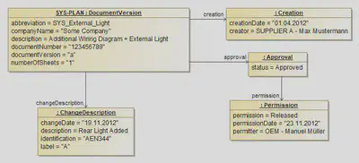
All information actually defined in a VEC file is contained in a DocumentVersion. Additionally this DocumentVersion carries all the meta-information about the underlying document (e.g. for a system schematic), This information is normally shown in drawings as a title block.
The DocumentVersion contains the information about the unique naming, a multilingual description, the DocumentNumber and so on. It has subelements to define the change history (ChangeDescription), the creation and the different approvals.
Information from the Title Block in VEC - according to ISO 7200
The title block in drawings contains information which identifies the shown construction and documents the authorship and the responsibility. In addition to that, further information can be shown in this title block e.g. for used IT systems. General requirements for data fields in the title block are regulated in the standard ISO 7200. Due to the fact that the VEC supports the modelling of drawing contents, these requirements can also be stored in the VEC.
The ISO requirements are shown in the tables below and in the last column the mapping to the VEC model can be found.
Identifying data fields in the title block
| Field name (from ISO 7200) | Obligation | Description | Mapping to VEC |
|---|---|---|---|
| Legal owner | M | The name of the legal owner of the document, e.g. firm, company, enterprise. It could be the official owner’s name, an abridged trade name or a logotype for the presentation. | DocumentVersion.CompanyName |
| Identification number | M | The document identification number is used as the reference to the document. The identification number shall be unique — at least within the organization of the legal owner. | DocumentVersion.DocumentNumber |
| Revision index | O | The revision index identifies the revision status of the document. Different versions are numbered in consecutive order by means of, e.g. a letter or letter combination A to Z, then AA, AB, AC … or Figures 1, 2,3 … The letters I and O should be avoided because they are easily confused with the digits 1 and 0. Alternatively, the date of issue field only may be used. | DocumentVersion.DocumentVersion |
| Date of issue | M | The date of issue is the date on which the document is officially released for the first time, and that of every subsequent released version. It is when the document is made available for its intended use. The date of issue is important for legal reasons, e.g. patent rights, traceability. | DocumentVersion.Creation.CreationDate |
| Segment/sheet number | M | The segment/sheet number identifies the segment or sheet. | DocumentVersion.SheetOrChapter.SheetNumber |
| Number of segments/sheets | O | This is the total number of segments or sheets of which the document consists. | DocumentVersion.NumberOfSheets |
| Language code | O | The language code is used to indicate the language in which the language-dependent parts of the document are presented. | Not needed – each field value will be represented by a ‘LocalizedString’ or ‘LocalizedTypedString’ |
Descriptive data fields in the title block
| Field name (from ISO 7200) | Obligation | Description | Mapping to VEC |
|---|---|---|---|
| Title | M | The title refers to the content of the document. | LocalizedTypedString with the type ‚Title‘ in DocumentVersion.Description (see below) |
| Supplementary title | O | The supplementary title field may be used to give further information on the object, when needed | LocalizedTypedString with the type ‚SupplementaryTitle ‘ in DocumentVersion.Description (see below) |
All Attributes in the VEC with the type AbstractLocalizedString can be realized either with an instance from the class LocalizedString or LocalizedTypedString. While the LocalizedString must be used just once for each attribute and language code the LocalizedTypedString must be used once for each attribute and language code AND each type. The OpenEnumertation LocalizedTypedStringType enables the possibility to place e.g. the title and the supplementary title for e.g. ‘En’ in the description mapping.
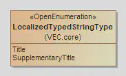
| |
Administrative data fields in the title block
| Field name (from ISO 7200) | Obligation | Description | Mapping to VEC |
|---|---|---|---|
| Responsible department | O | The name or code for the organizational unit responsible for the contents and maintenance of the document at the date of release. | DocumentVersion.Creation –> ResponsibleDesigner.Department |
| Technical reference | O | The name of the person having sufficient knowledge of the technical contents of the document to be named as the contact person and who will answer, coordinate and act on queries. | DocumentVersion.Creation –> ResponsibleDesigner.Lastname |
| Approval person | M | The name of the person who approved the document. The document might have been checked by a number of different specialists in accordance with the local rules for that type of document, specific project etc. The names of such specialists may be indicated in the title block or in a separate document part. | DocumentVersion.Approval –> Permission.Permitter.LastName \ \ If a different number of different specialists have checked the document, an instance of Approval each can be used and the attribute levelOfApproval names the effective scope |
| Creator | M | The creator or person who has prepared or revised the document. | DocumentVersion.Creation.Creator.LastName |
| Document type | M | The document type field indicates the role of the document with respect to its content of information and representation format. | DocumentVersion.DocumentType |
| Classification/key words | O | The text or code to categorize the contents of the document used for retrieval. | |
| Document status | O | The document status indicates where the document is in its life cycle. The status is indicated by means of terms such as “In preparation”, “Under approval”, “Released” and “Withdrawn”. | DocumentVersion.Approval.Status |
| Page number | O | The page number is usually generated by the presentation system. | DocumentVersion.SheetOrChapter.SheetNumber |
| Number of pages | O | The number of pages is dependent on the presentation format used, e.g. text font, paper size and character size. | DocumentVersion.NumberOfSheets |
| Paper size | O | The size of the form for the original document, e.g. A4. | DocumentVersion.SheetOrChapter.SheetFormat |
Item History
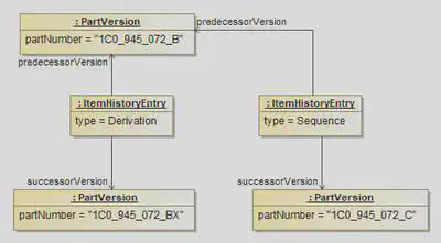
This example demonstrates how chronological relationships between PartVersion can be established. The VEC offers two types of relationships:
- Derivation: Derivation means that the successor of the relationship is a newly developed part (variant) based on an existing part.
- Sequence: Sequence means that the successor is a replacement for the predecessor.
Electrological Layers

The VEC offers three layer, each representing a level of abstraction for describing electrologic. This is illustrated in the diagram on the right side (Figure 1).
The Architectural Layer defines the connectivity / communication links (see Net) between components, without making any specifications regarding the physical realization. For example, this layer can be used to define which Bus technologies used by E/E components and the network topology to communicate with each other. To describe this layer in the VEC, the NetSpecification and its subelements are used.
The System Schematic Layer is more detailed than the Architectural Layer. The electrological realization of the Nets from the Architectural Layer are defined. Nets from Architectural Layer are realized by Connections. A connection has a defined electrical potential (see Signal). For example a “Body CAN Bus”, represented by a single Net in the Architectural Layer, has the two electrical potentials, “Body CAN High” and “Body CAN Low”. In the System Schematic Layer those are represented by two individual Connections.
However, the System Schematic Layer does not define a specific physical realization of the connectivity. A Connection with three ends (like in the diagram on the right) could be realized in many ways (e.g. a splice, a distribution component (star link), a double crimp, an IDC connection, …). To describe this layer in the VEC, the ConnectionSpecification and its subelements are used.
The Wiring Layer specifies a concrete physical realization of the layers above and narrows their degrees of freedom. It is getting more concrete (e.g. it defines the realization of the connection with three ends from the diagram on the right by a splice). Typically the Wiring Layer contains information such as wire colors, cross section areas, conductor and plating materials.
Due to its similarity, the Wiring Layer uses the same basic model elements as the definition of concrete harness. However, the flexibility of the VEC model allows the Wiring Layer to leave aspects unspecified. For example, by using PartUsages instead of PartOccurrences, partial WireSpecifications can be used instead of concrete PartVersions to describe the wiring. This makes it possible, for example, to define wire cross-sections and colors without having to specify insulation materials.
Many processes define documents that are similar to this layered structure in terms of their content, but do not correspond to it one hundred percent. This means, for example, that a process document “System Schematic” might contain many aspects of the VEC layer “System Schematic”, but can also define additional information from the VEC Layer “Wiring”.
This is perfectly valid and an intended feature of the VEC.
Architectural Layer
Disclaimer: This page or section is currently under review by the community.
The content of this page or section can be subject to change at any time. If you find any issues or if you have any review comments please drop us an issue in our Issue Management on GitHub.
This page or section resolves #573
Basic Architectural Layer
The Architectural Layer is the highest abstraction layer for describing electrological aspects in the VEC. It focuses on defining the connectivity between components without specifying the physical realization of that connectivity. This layer is particularly useful for early design phases, where the overall system architecture needs to be established without delving into implementation details.

The figure above illustrates a simple sketch of a “Power Window (Driver Side)” system in the architectural layer. It shows the main components involved (Body Controller, Door Module Driver, and Power Window Engine Driver) and the communication links between them. However, it does not specify how these connections are physically realized (e.g., electrical potentials, wire types, connectors). The instantiation of this sketch in the VEC is shown in the figure below.

The VEC instantiation in this example contains slightly more detail than the sketch, but still refrains from defining physical realization aspects. The VEC elements used to describe the Architectural Layer are contained in the NetSpecification. Each E/E Component is represented by a NetworkNode. The communication links between the components are represented by three Nets. A Net is the usage of a NetType, e.g., “CAN Bus” or “HALL”, defining the technology used for communication. The Net defines a specific instance of this technology in the system, e.g., “Body-CAN Bus” or “HALL for Power Window Driver Side”.
The XML representation of the above example within the NetSpecification is shown below:
<?xml version="1.0" ?>
<vec:VecContent xmlns:xsi="http://www.w3.org/2001/XMLSchema-instance" xmlns:vec="http://www.prostep.org/ecad-if/2011/vec" id="Content_00000" xsi:schemaLocation="">
  <VecVersion>2.2.0</VecVersion>
  <GeneratingSystemName>VEC Samples</GeneratingSystemName>
  <DateOfCreation>2025-11-03T14:05:24.068903900Z</DateOfCreation>
  <GeneratingSystemVersion>0.0.1</GeneratingSystemVersion>
  <DocumentVersion id="DocumentVersion_00001">
    <CompanyName>Acme Inc.</CompanyName>
    <DocumentNumber>1234567</DocumentNumber>
    <DocumentType>NetworkArchitecture</DocumentType>
    <DocumentVersion>a</DocumentVersion>
    <Specification xsi:type="vec:NetSpecification" id="NetSpecification_00002">
      <Identification>NETWORK</Identification>
      <Net id="Net_00003">
        <Identification>PWED-Engine</Identification>
        <NetType>NetType_00006</NetType>
        <NetworkPort>NetworkPort_00017 NetworkPort_00014</NetworkPort>
      </Net>
      <Net id="Net_00004">
        <Identification>HALL</Identification>
        <NetType>NetType_00007</NetType>
        <NetworkPort>NetworkPort_00016 NetworkPort_00013</NetworkPort>
      </Net>
      <Net id="Net_00005">
        <Identification>Body-CAN</Identification>
        <NetType>NetType_00008</NetType>
        <NetworkPort>NetworkPort_00010 NetworkPort_00012</NetworkPort>
      </Net>
      <NetType id="NetType_00006">
        <Identification>12V-Power</Identification>
        <SignalType>Energy</SignalType>
      </NetType>
      <NetType id="NetType_00007">
        <Identification>HALL</Identification>
        <SignalType>Information</SignalType>
        <SignalInformationType>Analog</SignalInformationType>
      </NetType>
      <NetType id="NetType_00008">
        <Identification>CAN</Identification>
        <SignalType>Information</SignalType>
        <SignalSubType>CAN</SignalSubType>
        <SignalInformationType>Digital</SignalInformationType>
      </NetType>
      <NetworkNode id="NetworkNode_00009">
        <Identification>BCM</Identification>
        <Port id="NetworkPort_00010">
          <Identification>CAN1</Identification>
          <NetType>NetType_00008</NetType>
        </Port>
      </NetworkNode>
      <NetworkNode id="NetworkNode_00011">
        <Identification>DMD</Identification>
        <Port id="NetworkPort_00012">
          <Identification>CAN</Identification>
          <NetType>NetType_00008</NetType>
        </Port>
        <Port id="NetworkPort_00013">
          <Identification>PWED-HALL</Identification>
          <NetType>NetType_00007</NetType>
        </Port>
        <Port id="NetworkPort_00014">
          <Identification>PWED-Engine</Identification>
          <NetType>NetType_00006</NetType>
        </Port>
      </NetworkNode>
      <NetworkNode id="NetworkNode_00015">
        <Identification>PWED</Identification>
        <Port id="NetworkPort_00016">
          <Identification>HALL</Identification>
          <NetType>NetType_00007</NetType>
        </Port>
        <Port id="NetworkPort_00017">
          <Identification>Engine</Identification>
          <NetType>NetType_00006</NetType>
        </Port>
      </NetworkNode>
    </Specification>
  </DocumentVersion>
</vec:VecContent>
Transition to System Schematic Layer
The system schematic layer is one abstraction level below the architectural layer. It adds more detail to the connectivity defined in the architectural layer by differentiating the electrical potentials and connections between components, while still not delving into physical realization details, e.g. wire colors or cross sections. More details regarding the system schematic layer can be found in the System Schematic Layer guideline. This transition is illustrated in the figure below.

To maintain clarity, we build upon the previous example of the architectural layer, but with a focus on just the HALL network and its two participants, the DMD and PWED. A HALL-sensor signal typically consists of three electrical potentials: a power supply voltage, a ground reference, and the actual signal output. In the architectural layer, this entire communication link is represented by a single Net named “PWED-HALL”. However, in the system schematic layer, this link is broken down into three distinct Connections, each representing one of the electrical potentials involved in the HALL communication. Also note, that the ComponentNode has a ComponentPort for each electrical potential. These ports are grouped under a ComponentConnector.
The figure belows shows the VEC instantiation of the system schematic layer and the tracability into the network layer, but only for the PWED side and a single connection in order to avoid cluttering of the diagram. Also note that the figure contains Signals as the pyhsical pendants of the NetType.

The XML representation of the above example within the ConnectionSpecification is shown below. This is a partial extract focusing on the connections related to the HALL network and extends the previous XML example for the architectural layer:
[...]
    <Specification xsi:type="vec:SignalSpecification" id="SignalSpecification_00018">
      <Identification>SIGNALS</Identification>
      <Signal id="Signal_00019">
        <Identification>PWED_HALL_GROUND</Identification>
        <SignalType>Ground</SignalType>
        <NetType>NetType_00007</NetType>
      </Signal>
      <Signal id="Signal_00020">
        <Identification>PWED_HALL_IN</Identification>
        <SignalType>Energy</SignalType>
        <NetType>NetType_00007</NetType>
      </Signal>
      <Signal id="Signal_00021">
        <Identification>PWED_HALL_OUT</Identification>
        <SignalInformationType>Analog</SignalInformationType>
        <SignalType>Information</SignalType>
        <NetType>NetType_00007</NetType>
      </Signal>
    </Specification>
    <Specification xsi:type="vec:ConnectionSpecification" id="ConnectionSpecification_00022">
      <Identification>SCHEMATIC</Identification>
      <ComponentNode id="ComponentNode_00023">
        <Identification>DMD</Identification>
        <NetworkNode>NetworkNode_00011</NetworkNode>
        <ComponentConnector id="ComponentConnector_00024">
          <Identification>A</Identification>
          <ComponentPort id="ComponentPort_00025">
            <Identification>1</Identification>
            <NetworkPort>NetworkPort_00013</NetworkPort>
          </ComponentPort>
          <ComponentPort id="ComponentPort_00026">
            <Identification>2</Identification>
            <NetworkPort>NetworkPort_00013</NetworkPort>
          </ComponentPort>
          <ComponentPort id="ComponentPort_00027">
            <Identification>3</Identification>
            <NetworkPort>NetworkPort_00013</NetworkPort>
          </ComponentPort>
        </ComponentConnector>
      </ComponentNode>
      <ComponentNode id="ComponentNode_00028">
        <Identification>PWED</Identification>
        <NetworkNode>NetworkNode_00015</NetworkNode>
        <ComponentConnector id="ComponentConnector_00029">
          <Identification>A</Identification>
          <ComponentPort id="ComponentPort_00030">
            <Identification>1</Identification>
            <NetworkPort>NetworkPort_00016</NetworkPort>
            <Signal>Signal_00019</Signal>
          </ComponentPort>
          <ComponentPort id="ComponentPort_00031">
            <Identification>2</Identification>
            <NetworkPort>NetworkPort_00016</NetworkPort>
            <Signal>Signal_00020</Signal>
          </ComponentPort>
          <ComponentPort id="ComponentPort_00032">
            <Identification>3</Identification>
            <NetworkPort>NetworkPort_00016</NetworkPort>
            <Signal>Signal_00021</Signal>
          </ComponentPort>
        </ComponentConnector>
      </ComponentNode>
      <Connection id="Connection_00033">
        <Identification>PWED_HALL_GROUND</Identification>
        <Net>Net_00004</Net>
        <Signal>Signal_00019</Signal>
        <ConnectionEnd id="ConnectionEnd_00034">
          <Identification>PWED.A.1</Identification>
          <IsExternalEnd>true</IsExternalEnd>
          <ConnectedComponentPort>ComponentPort_00030</ConnectedComponentPort>
        </ConnectionEnd>
        <ConnectionEnd id="ConnectionEnd_00035">
          <Identification>DMD.A.1</Identification>
          <IsExternalEnd>true</IsExternalEnd>
          <ConnectedComponentPort>ComponentPort_00025</ConnectedComponentPort>
        </ConnectionEnd>
      </Connection>
      <Connection id="Connection_00036">
        <Identification>PWED_HALL_IN</Identification>
        <Net>Net_00004</Net>
        <Signal>Signal_00020</Signal>
        <ConnectionEnd id="ConnectionEnd_00037">
          <Identification>PWED.A.2</Identification>
          <IsExternalEnd>true</IsExternalEnd>
          <ConnectedComponentPort>ComponentPort_00031</ConnectedComponentPort>
        </ConnectionEnd>
        <ConnectionEnd id="ConnectionEnd_00038">
          <Identification>DMD.A.2</Identification>
          <IsExternalEnd>true</IsExternalEnd>
          <ConnectedComponentPort>ComponentPort_00026</ConnectedComponentPort>
        </ConnectionEnd>
      </Connection>
      <Connection id="Connection_00039">
        <Identification>PWED_HALL_OUT</Identification>
        <Net>Net_00004</Net>
        <Signal>Signal_00021</Signal>
        <ConnectionEnd id="ConnectionEnd_00040">
          <Identification>PWED.A.3</Identification>
          <IsExternalEnd>true</IsExternalEnd>
          <ConnectedComponentPort>ComponentPort_00032</ConnectedComponentPort>
        </ConnectionEnd>
        <ConnectionEnd id="ConnectionEnd_00041">
          <Identification>DMD.A.3</Identification>
          <IsExternalEnd>true</IsExternalEnd>
          <ConnectedComponentPort>ComponentPort_00027</ConnectedComponentPort>
        </ConnectionEnd>
      </Connection>
    </Specification>
[...]
System Schematic
System Schematic Basics
The system schematic is used to illustrate the electrical components (e.g. ECUs, sensors or switches) in a vehicle electrical system and their connections to each other on an electrological level without physical realization details. In many companies the system schematic is specific for an individual system and not an individual vehicle variant. The example below shows such a system schematic with four components (MX1.1, MX3.1, MX3.2 and E1.1), which are connected to each other in some way. On the connection lines the potential names can be found. Furthermore the component E1.1 is connected to additional elements on another sheet / in another system, which is suggested by the arrow on the very bottom. This is explained in more details in the section Partial Systems.
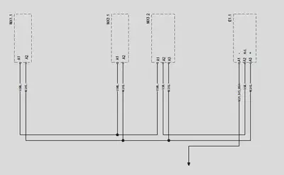
To represent a system schematic in the VEC the ConnectionSpecification and its subelements are used. E/E-Components (in some ECAD Systems called Block) are represented by ComponentNodes. A ComponentNode is a node where an electrological component is located. It is a representative for an element in the electric system, e.g. an actuator, a sensor, an ECU. This diagram contains the representation as VEC classes of the system schematic shown in the example. The ComponentPort (Pins) of a ComponentNode are grouped into Connectors / Slots with the help of ComponentConnectors. In the example the connectors are only represented implicitly by the prefix “A” to the Pin-Number.
Even if the system schematic in this example only shows pins which are connected to other pins (of other components), the VEC representation of the component (ComponentNode) is explicitly allowed to contain ComponentPorts for unused pins. For example a component with 5 pins where just pin no. 1 and 5 are connected in some way may contain ComponentPorts for the pins 2 - 4 (but is not required to). This underlines that these pins do physicaly exists. There is no need of a reference from a Connection to one of the ComponentPorts via a ConnectionEnd.
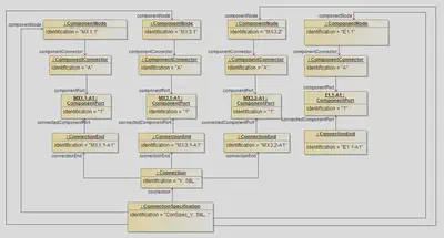
The following XML listing contains the component nodes and connection from the example above.
<Specification xsi:type="vec:ConnectionSpecification" id="id_connect_spec_1">
    <Identification>ConSpec_V..58L..</Identification>
    <ComponentNode id="id_comp_node_1">
        <Identification>MX1.1</Identification>
        <ComponentConnector id="id_component_connector_1">
            <Identification>A</Identification>
            <ComponentPort id="id_comp_port_1">
                <Identification>1</Identification>
            </ComponentPort>
        </ComponentConnector>
    </ComponentNode>
    <ComponentNode id="id_comp_node_2">
        <Identification>MX3.1</Identification>
        <ComponentConnector id="id_component_connector_2">
            <Identification>A</Identification>
            <ComponentPort id="id_comp_port_2">
                <Identification>1</Identification>
            </ComponentPort>
        </ComponentConnector>
    </ComponentNode>
    <ComponentNode id="id_comp_node_3">
        <Identification>MX3.2</Identification>
        <ComponentConnector id="id_component_connector_3">
            <Identification>A</Identification>
            <ComponentPort id="id_comp_port_3">
                <Identification>1</Identification>
            </ComponentPort>
        </ComponentConnector>
    </ComponentNode>
    <ComponentNode id="id_comp_node_4">
        <Identification>E1.1</Identification>
        <ComponentConnector id="id_component_connector_4">
            <Identification>A</Identification>
            <ComponentPort id="id_comp_port_4">
                <Identification>1</Identification>
            </ComponentPort>
        </ComponentConnector>
    </ComponentNode>
    <Connection id="id_connection_1">
        <Identification>V..58L..</Identification>
        <ConnectionEnd id="id_conn_end_1">
            <Identification>MX1.1-A1</Identification>
            <ConnectedComponentPort>id_comp_port_1</ConnectedComponentPort>
        </ConnectionEnd>
        <ConnectionEnd id="id_conn_end_2">
            <Identification>MX3.1-A1</Identification>
            <ConnectedComponentPort>id_comp_port_2</ConnectedComponentPort>
        </ConnectionEnd>
        <ConnectionEnd id="id_conn_end_3">
            <Identification>MX3.2-A1</Identification>
            <ConnectedComponentPort>id_comp_port_3</ConnectedComponentPort>
        </ConnectionEnd>
    </Connection>
    [...]
</Specification>
Potential Nodes
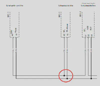
As mentioned before, the level of abstraction of the system schematic in the VEC (represented by the ConnectionSpecification) contains only the electrological design and no physical design of the wiring harness. Therefore, the black dots (circled in red) in the graphical example have only a layouting purpose and do not represent a technical design decision (e.g. to place a splice on this spot).
The expressed engineering intention is only that the connected pins (all “A1”) have the same potential (are connected in some way). The decision about a technical realization (e.g. splice, multicrimp, single wires) can not be made is most cases at the stage of a system schematic, because a technical realization depends on concrete variant combinations and might be even different for different variants (see section Wiring) or it can be unnecessary, because in a reduced 100% variant, there might be just two of the three components left and a realization with a single wire would be possible. As the VEC does not represent the graphical layout of documents these nodes have no representation in VEC.
If the system schematic should explicitly contain the engineering intention of a specific connection topology (e.g. a star like topology with a splice or a potential distributor) this must be explicitly represented by an individual design of one ore more ComponentNodes and Connections. Such a ComponentNode should have the ComponentNodeType = 'PotentialDistributor'. The illustrations below show the example of a CAN bus system with and without explicit distribution.


As you can see in the illustration of the central distributed CAN bus, the component node of the distributor “CAN” uses internal connections to represent the short-circuited pins. More information about internal conectivity can be found in this section below.
Partial Systems
During the development of individual systems or sub systems for a vehicle the corresponding system schematic is often incomplete (partial). This situation arises from the fact, that most systems depend on some kind of infrastructure of the integrated overall vehicle system (e.g. power, ground or bus connections), which is only a available in the context of the complete vehicle. In the example at the top such a link to an unspecified infrastructure is represented by the down arrow, in the following sections this is called an open link.
To create a fully functional system, a partial system must be merged / combined with other partial systems. In this process matching open links are connected (and thus removed) in order to create complete overall system. In the extended example this is illustrated by adding a second partial system schematic (framed in red) to the original example from the top. The resulting overall system schematic of such a merge process would just contain a simple connection between E.1.1 and M31.
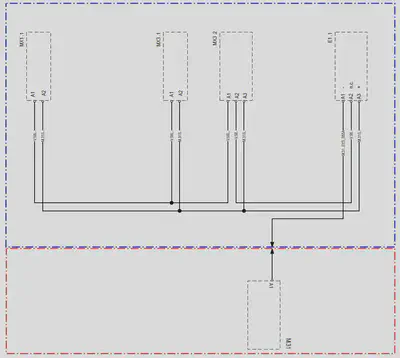
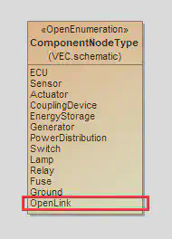
The mapping of this advanced schematic example into the VEC context it is the following (see this diagram).
- To maintain the logical grouping of each partial system schematic, the content of each is contained in its own
DocumentVersionwith a singleConnectionSpecificationin the sameVecContent. - The open link is represented by a “virtual”
ComponentNode. Its naming is arbitrary and shall be choosen in a way, that a merge algorithm has the required information. For the clarity of the example it is here named GROUND. Depending on the used merge algorithm the name can be irrelevant if the merge algorithm for example only requires signal information. - The “virtual” component node shall be marked with the
ComponentNodeTypeliteral OpenLink (see on the right).
This diagram shows the extended version with the ComponentNode “GROUND”. As you can see the ComponentNode is marked with the node type “OpenLink” (red mark) to clarify that this component is NOT part of the system schematic but components from the plan DO HAVE a connection to it.
Caution: The strategy and algorithm to merge partial systems if individual for the different ECAD systems and development processes. The VEC does not define an algorithm or requires a specific strategy. The VEC only the means to store and exchange the information that is required by those algorithms. When merging the definition of these partial systems together into one vehicle system, it is mandatory to resolve these open links and replace them by determined ComponentNode elements or Connection:
- Case 1: The open link component node is replaced by a real component with the required connectivity.
- Case 2: If multiple real component nodes have connections to different open link component nodes, the open link nodes can be merged to a single connection among the real component nodes.
Note: It is possible to reference a ComponentPort from a Connection.ConnectionEnd even if they are contained in different DocumentVersions.
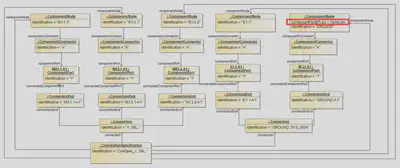
The following listing shows the additional ComponentNode as XML.
<Specification xsi:type="vec:ConnectionSpecification" id="id_connect_spec_1">
    <Identification>ConSpec_V..58L..</Identification>
    [...]
    <ComponentNode id="id_comp_node_4">
        <Identification>E1.1</Identification>
        <ComponentConnector id="id_component_connector_4">
            <Identification>A</Identification>
            <ComponentPort id="id_comp_port_4">
                <Identification>1</Identification>
            </ComponentPort>
        </ComponentConnector>
    </ComponentNode>
    <ComponentNode id="id_comp_node_5">
        <Identification>GROUND</Identification>
        <ComponentNodeType>OpenLink</ComponentNodeType>
        <ComponentConnector id="id_component_connector_5">
            <Identification>A</Identification>
            <ComponentPort id="id_comp_port_5">
                <Identification>1</Identification>
            </ComponentPort>
        </ComponentConnector>
    </ComponentNode>
    [...]
    <Connection id="id_connection_1">
        <Identification>GROUND..SYS_055A</Identification>
        <ConnectionEnd id="id_conn_end_1">
            <Identification>E1.1-A1</Identification>
            <ConnectedComponentPort>id_comp_port_4</ConnectedComponentPort>
        </ConnectionEnd>
        <ConnectionEnd id="id_conn_end_2">
            <Identification>GROUND-A1</Identification>
            <ConnectedComponentPort>id_comp_port_5</ConnectedComponentPort>
        </ConnectionEnd>
    </Connection>
</Specification>
Internal Connectivity
The system schematic layer in the VEC allows not only the mapping of Connections between different ComponentNodes, but also the mapping of internal connections within a ComponentNode. Examples are fuses, relays, power and potential distributors or fuse or relay carriers.

In the VEC these connections do not differ in modelling from ’normal’ ones in the level of abstraction of the system schematic. The only difference is the value of the flag isExternalEnd for their ConnectionEnds. The value of this flag has to be set from the ComponentPorts point of view and its relation to the Connection:
- If the
Connectionis attached from the outside to theComponentPort, e.g. it is a connection between two independentComponentNodes, then it isisExternalEnd = true. - If the connection is attached from the inside, e.g. it is a internal connection between two
ComponentPorts of the sameComponentNode, then it isisExternalEnd = false.
Inner Structure of Component Nodes
In the system schematic, components are often considered black boxes. However, there scenarios where this is not sufficient and a view on the inner structure is required. Therefore, ComponentNode can be structured hierarchically. This requirement is also the logical consequence of the concept of subdivided UsageNodes. Since ComponentNodes are representatives / realizations of UsageNodes, at least the same representation options are required here (see this implementation guideline for more details).
Sub ComponentNodes are located inside their parent node. Connections to the “outer world” are mostly realized via a ComponentConnector of the parent node and internal connectivity between the connector of the parent node and its children. The following graphic illustrates this situation. The internal connections are shown as red lines.

The “outer world” (e.g. a system schematic or a wiring harness) interacts only with the parent node (black box). However, there are use cases, e.g. after sales service, where it is relevant to know which element of the “outer world” (e.g. a wire or a pin) is connected to which sub node, e.g. “Which wire is the power supply of the direction indicator?”. The representation of this information in the VEC is explained in the following paragraphs.
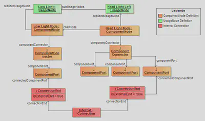
Both, parent node as well as child nodes are represented as ComponentNodes (highlighted in orange in the diagram above). The child ComponentNodes (e.g. “Low Light Node”) are contained in the parent ComponentNode (“Head Light Node”). A traceability to the corresponding UsageNode (highlighted in green) can be created with the realizedUsageNode association.
The parent and the child nodes define their electrical interface with ComponentConnectors and ComponentPorts. To represent the illustration, the parent node defines one ComponentConnector with three ComponentPorts, the child node defines one ComponentConnector with one ComponentPort. The internal connectivity is represented with a Connection between the ComponentPorts of the parent and the children (highlighted in red).
ConnectionEnds have different values for isExternalEnd. This is due to the fact that the end, that is connected to the port of the parent node, is on the inside (isExternal=false from the perspective of the port), the end that is connected to the inner node, is on the outside (isExternal=true).Variant Management For ECUs
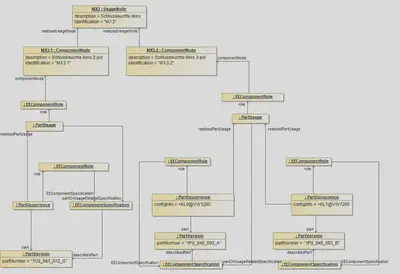
This example demonstrates how the variant management can be handled in the systems schematic on different levels of abstraction.
The top most element is the usage node. It defines an abstract position / function in the vehicle. In the example it is the back light on the left hand side (named “MX3”). This function can be realized by two different electrological variants (interfaces). These variants are represented by ComponentNodes. In the example there is one variant with two pins (MX3.1) and one variant with three pins (MX3.2). On a more concrete level these interfaces can be satisfied by one or more EE-components (alternatives). These EE-Components are defined by PartVersion with a EEComponentSpecification. In order to define restrictions a corresponding PartOccurrence with a VariantConfiguration can be defined.
The PartUsages in the example are needed for to reasons:
- They serve as a container to group the different possible alternatives (“realizedPartUsage”).
- It is necessary to declare one of the EEComponents as the representative of all alternatives of a variant. This is done by the reference between the PartUsage and the corresponding
EEComponentSpecification.
Wiring

The Wiring Layer in the VEC provides modeling concepts to define the physical realization of electrological connections from the System Schematic Layer. In the VEC, the same modeling concepts are use for this layer as for the mapping of a concrete wiring harness in the model.
However, in Wiring Layer representation the degree of freedom and number of unspecified facts are typically greater, than in a harness definition. For example the wiring layer would make statements about the cross section area of a wire or the color of its insulation, but it would not define a specific insulation material or wire length as the wiring layer is installation space agnostic in many development process.
Basically, there are three main modeling concepts:
- The description and instantiation of parts (e.g. connectors, wires, terminals).
- The contacting (marked with green dashed lines). It defines the relationship between terminals, wire ends and cavities.
- The coupling (marked with red dashed lines). This is for connecting connectors with E/E components or with each other, or even to connect E/E components with each other. It is explained in more detail in the guideline ““Coupling””
Description and Instantiation of Parts
In contrast to the Network Architecture and the System Schematic the Wiring Layer does not define its own level of abstraction, instead it utilizes the existing modeling concepts in the VEC to describe the physical properties of the electrologically relevant components.
It is possible to use concrete PartVersions in the Wiring Layer, but typically not all relevant properties are defined in the Wiring Layer, so mainly PartUsages will be used (detailed description can be found here).
Contacting
The contacting in the VEC defines the relationship between Cavities (CavityReference), WireEnds, Terminals and Seals. Since there are various types of contactings possible, the different types are not defined explicitly in the VEC. The VEC offers a quite generic structure (the Contacting), which should be able to support all the different possible types. This is necessary, because the different contacting types are driven by technical requirements and new contactings might emerge over the time. The downside of the generic structure is that the structural schema allows constellations that are not sensible from a technical point of view as well. The following sections show the different contacting types used today, and how they have to be implemented in the VEC.
Since the contacting can be used for different levels of abstraction (Product Definiton or Electrological Wiring) only the “Role-Side” of the necessary objects is shown. Necessary PartOrUsageRelatedSpecifications, PartOccurrences, PartUsages and PartVersion are omitted.
Standard Contact
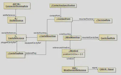
A standard Contacting is the most common case in a wiring harness. For a standard contact you have one wire end that has one terminal crimped on it, which is placed in one cavity. It exists in two variants, sealed and unsealed. The example displays the sealed variant, for the unsealed variant the CavitySealRole and the CavityPlugRole have to be omitted.
The contacting is defined by a ContactPoint, contained in a ContactingSpecification. It is possible (and recommended) to define multiple ContactPoints in one ContactingSpecification. Usally there exists one ContactingSpecification per DocumentVersion in the scope. So for example if the VEC-File represents a 150%-Harness definition, then you will have on ContactingSpecification for the complete harness.
A ContactPoint is defined as a point of exactly one electrical potential, which means all conducting components related to the ContactPoint are short-circuited.
The ContactPoint defines the terminal that is used for the contacting. It is then split up into two parts, the side of the crimp of the terminal (represented by the WireMounting) and the side of the terminal, which is placed in the cavity (represented by the CavityMounting). Since the example is about a sealed standard contact, the WireMounting displayed references exactly one CavitySealRole and one WireEnd, which means these two components are crimped together onto the terminal. On the other side the CavityMounting defines the Cavity in which the terminal will be placed. For a sealed environment it is necessary, that the Cavity is plugged with a CavityPlug, in case the Cavity is not occupied by a contacting. If the Cavity is occupied, the CavityMounting defines explicitly, which CavityPlugRoles are replaced by its existence.
Multi Crimp Contact
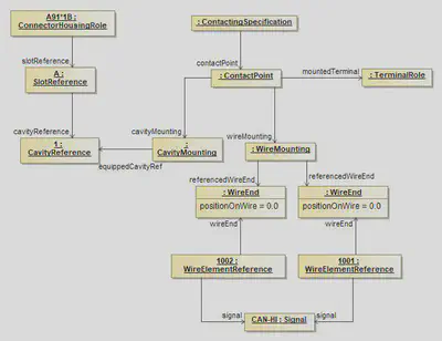
A Multicrimp is quite similar to the standard contact, with the difference that there is more than one wire crimped onto the terminal. Therefore the displayed example is quite the same. The differences are:
- There is no
CavityPlugRoleorCavitySealRole, since it is not usefull / possible from a technical point of view to seal a multicrimp. - There are two (or more)
WireEnds associated with theWireMounting.
For clarification of the example the two WireElementReferences reference their Signal. It is the same, since the two WireEnds are crimped onto one Terminal and therefore they are set to one single electrical potential. This is only displayed in the example in order to make it clear, what is meant by “A ContactPoint has one single electrical potential”. This is not a restriction of the VEC, since the development processes might need (or create) different signal names for the same electrical potential.
Ringterminal - Splice
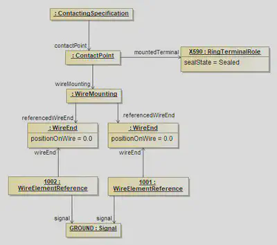
The structure displayed in the example applies to ring terminals and splices as well. On the side of the wire it is the same as a multi crimp. The difference is that no cavity mounting is used, since a ring terminal / splice has no cavities.
Bridge Terminal
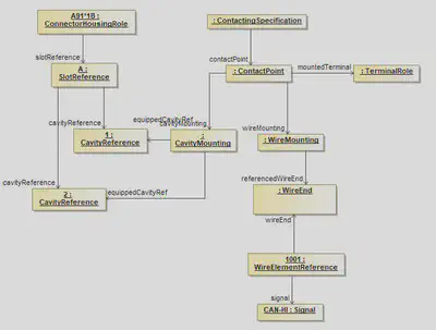
A bridge terminal is a terminal that has a wire crimped on it and which occupies more than one cavity (short-circuited). On the side of the wire it is the same as a standard contact. On the side of the cavities it simply references more than one cavity.
Coax Contact
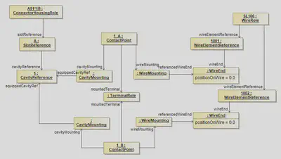
The diagram displays the proper definition of a coax contacting. In the case of coax contact one single terminal is used, but two different electrical potentials are connected to it. Therefore two ConcactPoints are required, because one ContactPoint can only be used for one electrical potential (see the definition of a ConcactPoint).
Both ContactPoints reference the same occurrence of the terminal (TerminalRole) and use the Cavity. Each ConcatPoint mounts a single WireElement to the TerminalRole. In this example the two WireElements belong to the same multi-core wire.
In order to make the example more clearly, the next figure displays the definition of such a “coax-cavity” in an EEComponent.
Coax Cavity
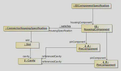
The HousingComponent of an EEComponent defines on one hand the pins (electrological relevant information) in this HousingComponent and on the other hand a ConnectorHousingSpecification (the layout and design of the HousingComponent). The PinComponents are then positioned in the cavities. In the case of a coax contact, two PinComponents (the different electrical potentials) are placed in one cavity.
The HousingComponent of an EEComponent defines on one hand the pins (electrological relevant information) in this HousingComponent and on the other hand a ConnectorHousingSpecification (the layout and design of the HousingComponent). The PinComponents are then positioned in the cavities. In the case of a coax contact, two PinComponents (the different electrical potentials) are placed in one cavity.
Direct Connectivity
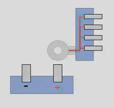
As is to be expected for the design of wiring harnesses, most of the electrological connections of a system schematic are realized by wires. However, there are also cases where such connections are also realized without wires, e.g. with a direct screwing connection or simple plugging of two E/E components. The most common use case of such directly connected components are fuses which are plugged into a slot of a fuse carrier. Another example is the battery isolator (German: “Batterietrennelement”), illustrated on the right side. The battery isolator is connected directly to the battery with an integrated ring terminal, that is screwed onto the bolt of the battery. The representation of this szenario is explained in the following paragraphs.
Mapping in the Wiring Layer
Each of the E/E component instances is build up in the same way as seen in this diagram. A EEComponentRole has got one or more HousingComponentReferences with underlying PinComponentReferences for the pins. To make statements about the technical details of such a pin, a TerminalRole is used.
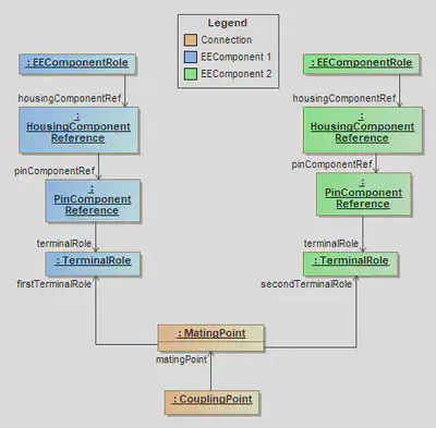
For the electrological connection / mapping of two pins, a MatingPoint is required, which creates the relation between the corresponding TerminalRoles. The MatingPoints are contained within a CouplingPoint in the CouplingSpecification. A CouplingPoint contains all MatingPoints for a single HousingComponentReference / ConnectorHousingRole (a detailed description can be found in the recommendation chapter Coupling Specification).
Note: In case of a terminal with multiple terminal receptions (with the possibility of separated potentials) a MatingDetail shall be used to define the mapping between specific TerminalReceptionReferences.
A detailed description of E/E components can be found in this tutorial.
Traceability to the System Schematic Layer
The system schematic layer contains no details about the physical realization. Therefore, no distinction is made in the system schematic layer between direct connections and wired connection. It is even possible to have different realizations of the same system schematic, one with a direct connection and one with a wired connection.
A detailed description to the system schamtic layer can be found in this tutorial.
To preserve traceability between the wiring layer and the system schematic, the element that realizes the the Connection has a reference to it. For a wired connection, this is the WireElementReference. In case of a direct connection, this is the MatingPoint or MatingDetail, depending on which level an unambiguous statement can be made. The following XML excerpt contains an example of traceability.
<Specification xsi:type="vec:CompositionSpecification" id="id_composition_1">
    <Component id="id_component_1">
        <Identification>Battery</Identification>
        [...]
        <Role xsi:type="vec:EEComponentRole" id="id_ee_role_1">
            <Identification>Battery</Identification>
            <EEComponentSpecification>id_ecomponent_spec_1</EEComponentSpecification>
            <HousingComponentRef id="id_housing_comp_ref_1">
                <Identification>A</Identification>
                <HousingComponent>id_housing_comp_1</HousingComponent>
                <ConnectorHousingRole id="id_conHousingRole_1">
                    <ConnectorHousingSpecification>id_connect_hous_spec_1</ConnectorHousingSpecification>
                    <SlotReference xsi:type="vec:SlotReference" id="id_slotRef_1">
                        <ReferencedSlot>id_slot_1</ReferencedSlot>
                        <CavityReference id="id_cavityRef_1">
                            <Identification>1</Identification>
                            <ReferencedCavity>id_cavity_1</ReferencedCavity>
                        </CavityReference>
                        [...]
                    </SlotReference>
                </ConnectorHousingRole>
                <PinComponentRef id="id_pin_comp_ref_1">
                    <PinComponent>id_pin_comp_1</PinComponent>
                    <TerminalRole xsi:type="vec:TerminalRole" id="id_terminalRole_1">
                        <Identification>1</Identification>
                        <TerminalSpecification>id_terminal_spec_1</TerminalSpecification>
                    </TerminalRole>
                </PinComponentRef>
                [...]
            </HousingComponentRef>
        </Role>
    </Component>
    <Component id="id_component_2">
        <Identification>Isolator</Identification>
        [...]
        <Role xsi:type="vec:EEComponentRole" id="id_ee_role_2">
            <Identification>Isolator</Identification>
            <EEComponentSpecification>id_ecomponent_spec_2</EEComponentSpecification>
            <HousingComponentRef id="id_housing_comp_ref_2">
                <Identification>A</Identification>
                <HousingComponent>id_housing_comp_2</HousingComponent>
                <ConnectorHousingRole id="id_conHousingRole_2">
                    <ConnectorHousingSpecification>id_connect_hous_spec_1</ConnectorHousingSpecification>
                    <SlotReference xsi:type="vec:SlotReference" id="id_slotRef_2">
                        <ReferencedSlot>id_slot_2</ReferencedSlot>
                        <CavityReference id="id_cavityRef_2">
                            <Identification>1</Identification>
                            <ReferencedCavity>id_cavity_2</ReferencedCavity>
                        </CavityReference>
                    </SlotReference>
                    [...]
                </ConnectorHousingRole>
                <PinComponentRef id="id_pin_comp_ref_2">
                    <PinComponent>id_pin_comp_2</PinComponent>
                    <TerminalRole xsi:type="vec:TerminalRole" id="id_terminalRole_2">
                        <Identification>1</Identification>
                        <TerminalSpecification>id_terminal_spec_2</TerminalSpecification>
                    </TerminalRole>
                </PinComponentRef>
            </HousingComponentRef>
            [...]
        </Role>
    </Component>
</Specification>
[...]
<Specification xsi:type="vec:CouplingSpecification" id="id_coupling_1">
    <CouplingPoint>
        <Identification>Battery-Isolator</Identification>
        <FirstConnector>id_conHousingRole_1</FirstConnector>
        <SecondConnector>id_conHousingRole_2</SecondConnector>
        <MatingPoint>
            <Identification>Mating-Battery-Isolator</Identification>
            <FirstTerminalRole>id_terminalRole_1</FirstTerminalRole>
            <SecondTerminalRole>id_terminalRole_2</SecondTerminalRole>
            <Connection>id_connection_1</Connection>
        </MatingPoint>
    </CouplingPoint>
</Specification>
[...]
<Specification xsi:type="vec:ConnectionSpecification" id="id_connect_spec_1">
    <Identification>ConSpec</Identification>
    <Connection id="id_connection_1">
        <Identification>PowerDistribution</Identification>
        <ConnectionEnd id="id_conn_end_1">
            <Identification>Battery</Identification>
            <ConnectedComponentPort>id_comp_port_1</ConnectedComponentPort>
        </ConnectionEnd>
        <ConnectionEnd id="id_conn_end_2">
            <Identification>Isolator</Identification>
            <ConnectedComponentPort>id_comp_port_2</ConnectedComponentPort>
        </ConnectionEnd>
    </Connection>
    [...]
</Specification>
Coupling Devices
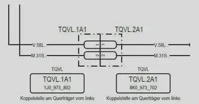
In the context of the VEC, a coupling device is:
… the (virtual) device that separates / connects two or more wiring harnesses. “Virtual” because it can be interpreted as a device / interface definition between the harnesses, where one harness behaves like an E/E component form the point of view of the other harness1.
That means, at a coupling device a larger electrical system is divided into multiple harnesses. There can be various reasons for such a division and depending on these reasons, coupling devices can be defined at different points in the development process. Often there are assembly requirements that make a subdivision necessary (e.g. between the door and main body). If an electrical connection is defined between those separate installation spaces, it crosses a coupling device and is split up at this point. Whether a connection crosses such a coupling device or not can often be only determined after the routing process in a concrete context of the packaging of a specific vehicle. Such coupling devices are often only relevant in a geometry / topology perspective and for the wiring of a specific harness and not in an architectural or system schematic layer.
However, there are also coupling devices that serve other purposes and therefore, must be defined early in the electrological branches of the development processes, i.e. in the architecture layer or the system schematic. A schematic diagram of such coupling device can be found in the figure above and will be example for the following sections.
Basic Concept
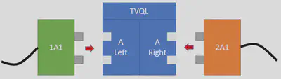
The basic idea for a mapping in the VEC for such coupling points between different harnesses is, to consider them as virtual E/E components with an internal connectivity. When looking at such a point on a real wiring harness, we will just see two or more connectors that are plugged into each other. However, the definition of a virtual component between these connectors in the product model creates multiple advantages:
- The representation in the system schematic is analogous to other E/E components. Traceability with the wiring layer can be achieved in a uniform way.
- When just looking at a single wiring harness, all connectors can be connected to an E/E component, no connectors are “hanging in thin air”.
- The virtual E/E component can be used as an interface contract and a point of separation between different development and process partners or even development lifecycles. For example, the wiring harness of a seat does not need to “know” everything about the complete electrical network of the vehicle. It just requires an interface definition of the E/E component “rest of the vehicle”.
- The virtual E/E component can be used to enforce standards for specific coupling points, for example a consistent pinning between the doors and the main body across multiple carlines.
System Schematic
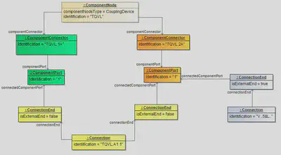
The figure above illustrates minimal representation of a coupling device in the system schematic with just one connector and only one pin on each side. The coupling device itself is represented in the VEC with a ComponentNode with the ComponentNodeType ='CouplingDevice'. For each side of the coupling device it contains a ComponentConnector. These connectors include the ComponentPorts, which represent the pins of the connector.
The connectivity between the port on each side is represented with a internal Connection with two ConnectionEnds, which reference the connected ComponentPorts. The flag isExternalEnd of the Ends is set to false, because the connection represents the internal mapping of ports within the coupling device. Connections to other ComponentNodes would be represented by different Connections with ConnectionEnds where isExternal=true.
Document Structure
Like with any self-contained piece of information in the VEC, for traceability reasons the definition of a _coupling device should be in the correct DocumentVersion. Section General Structure explains the general concept of DocumentVersion and their containments. As described there, the containment of Specifications in their DocumentVersions has a semantic meaning. The correct placement of a coupling device in a containing DocumentVersion is a perfect example for that.
Depending on the engineering process, system schematic relevant coupling device might be defined in some kind of master data process, enforcing standardized coupling devices for a specific scope. In that case, one or more of those standardized coupling devices would be managed and published together, and then reused in a specific system schematic. This is illustrated in the figure “Information Structure” below, on the left side of the figure.
On the other, it would also be perfectly valid to have no company wide management process for coupling devices. In this case, the coupling devices would be defined implicitly within a system schematic. This is illustrated on the right side of the figure.

XML Example
The XML snippet below contains the portions of a coupling device definition that belong to the system schematic layer.
<DocumentVersion id="id_docu_ver_16475">
  <Description xsi:type="vec:LocalizedString" id="id_16476">
    <LanguageCode>De</LanguageCode>
    <Value>Definition der Trennstelle TQVL</Value>
  </Description>
  <DocumentNumber>TQVL</DocumentNumber>
  <DocumentVersion>1</DocumentVersion>
  <DocumentType>MasterDataDefinition</DocumentType>
  <DataFormat>VEC</DataFormat>
  <Specification xsi:type="vec:ConnectionSpecification" id="id_connect_spec_1">
    <Identification>ConSpec_TZY5-DV12a</Identification>
    <ComponentNode id="id_comp_node_6">
      <Identification>TQVL</Identification>
      <ComponentNodeType>CouplingDevice</ComponentNodeType>
      <RealizedUsageNode>[id ref to usage node]</RealizedUsageNode>
      <ComponentConnector id="id_component_connector_1">
        <Identification>TQVL.1A</Identification>
        <ComponentPort id="id_component_port_1">
          <Identification>1</Identification>
        </ComponentPort>
      </ComponentConnector>
      <ComponentConnector id="id_component_connector_2">
        <Identification>TQVL.2A</Identification>
        <ComponentPort id="id_component_port_2">
          <Identification>1</Identification>
        </ComponentPort>
      </ComponentConnector>
    </ComponentNode>
    <Connection id="id_connection_1">
      <Identification>TQVL.A1</Identification>
      <ConnectionEnd id="id_conn_end_1">
        <Identification>TQVL.A.1</Identification>
        <IsExternalEnd>false</IsExternalEnd>
        <ConnectedComponentPort>id_component_port_1</ConnectedComponentPort>
      </ConnectionEnd>
        <ConnectionEnd id="id_conn_end_2">
        <Identification>TQVL.A.2</Identification>
        <IsExternalEnd>false</IsExternalEnd>
        <ConnectedComponentPort>id_component_port_2</ConnectedComponentPort>
      </ConnectionEnd>
    </Connection>
  </Specification>
</DocumentVersion>
Wiring
Traceability
Even without having an explicit coupling device definition (with a virtual E/E component) in the wiring layer, a traceability over a coupling device from one wiring harness to another is possible with the help of the system schematic layer.
Taking the ComponentNode Definition from above as a foundation, it is only necessary to create the traceability relations from the harness connectors to the system schematic layer, as illustrated in the figure below.
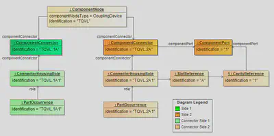
Below is the corresponding XML snippet.
<Component id="component_1">
  <Identification>TQVL.1A1</Identification>
  <Role xsi:type="vec:ConnectorHousingRole" id="connectorHousingRole_1">
    <Identification>TQVL.1A1</Identification>
    <ConnectorHousingSpecification>connectorHousingSpecification_1</ConnectorHousingSpecification>
    <ConnectedComponentConnector>id_component_connector_1</ConnectedComponentConnector>
    <SlotReference xsi:type="vec:SlotReference" id="slotRef_1">
      <Identification>A</Identification>
      <ReferencedSlot>slot_1</ReferencedSlot>
      <CavityReference id="cavityRef_1">
        <Identification>1</Identification>
        <ReferencedCavity>cavity_1</ReferencedCavity>
      </CavityReference>
    </SlotReference>
  </Role>
  [...]
</Component>
<Component id="component_2">
  <Identification>TQVL.2A1</Identification>
  <Role xsi:type="vec:ConnectorHousingRole" id="connectorHousingRole_2">
    <Identification>TQVL.2A1</Identification>
    <ConnectorHousingSpecification>connectorHousingSpecification_2</ConnectorHousingSpecification>
    <ConnectedComponentConnector>id_component_connector_2</ConnectedComponentConnector>
    <SlotReference xsi:type="vec:SlotReference" id="slotRef_2">
      <Identification>A</Identification>
      <ReferencedSlot>slot_2</ReferencedSlot>
      <CavityReference id="cavityRef_2">
        <Identification>1</Identification>
        <ReferencedCavity>cavity_2</ReferencedCavity>
        <ConnectedComponentPort>id_component_port_2</ConnectedComponentPort>
      </CavityReference>
    </SlotReference>
  </Role>
  [...]
</Component>
<Component id="component_3">
  <Identification>TQVL.2A2</Identification>
  <Role xsi:type="vec:ConnectorHousingRole" id="connectorHousingRole_3">
    <Identification>TQVL.2A2</Identification>
    <ConnectorHousingSpecification>connectorHousingSpecification_2</ConnectorHousingSpecification>
    <ConnectedComponentConnector>id_component_connector_2</ConnectedComponentConnector>
    <SlotReference xsi:type="vec:SlotReference" id="slotRef_3">
      <Identification>A</Identification>
      <ReferencedSlot>slot_2</ReferencedSlot>
      <CavityReference id="cavityRef_3">
        <Identification>1</Identification>
        <ReferencedCavity>cavity_2</ReferencedCavity>
      </CavityReference>
    </SlotReference>
  </Role>
  [...]
</Component>
see
ComponentNodeType↩︎
Product Definition of a Harness
The definition of the product itself (the wiring harness) is one of the major use cases of the VEC. The figure below illustrates the basic building blocks in the data model and provides guidance on where to look for specific topics. It is not a complete map of the VEC.

A wiring harness consists of recurring components that are produced and installed in large quantities (e.g., connectors, wires, terminals, and seals). These components have properties that are the same for all components of a specific type and are independent of their usage. In most cases, such types are identified within a company context as parts with unique part numbers. The description of these common properties is often referred to as “Part Master Data”. The “Component Specification / Part Master Data” section (blue box on the right-hand side) represents this information. This area is explained in more detail in the section “Component Specification”.
A wiring harness definition is then formed by specific uses of those component types, and a component can also occur multiple times. Each instance of a component may have additional properties specific to its usage (e.g., the signal and length of a wire, or the name of a connector). These properties are defined in the “Instances of Components” block, highlighted in green. In this area, the VEC distinguishes between abstract instances of components (PartUsage), where a specific component is not yet defined but some properties are known, and instances of concrete components (PartOccurrence). See “Instances of Components” for more details.
Based on these instances, you can specify bills of materials (BOMs), with or without variance, for composite parts, which can in turn be used hierarchically as instances for more complex parts (block on the right-hand side, highlighted in orange). See “Composite Parts” for more details.
In addition to the BOM view, it is important to establish relationships between components and other elements of the wiring harness definition (e.g., topology or electrology). This is accomplished through “Behaviour & Relationship Definitions” (highlighted in violet), which specify relationships such as routing, placement, contacting, and traceability between components and definitions at higher levels of abstraction.
Harness Description Document Structure and Typical Content
Disclaimer: This page or section is currently under review by the community.
The content of this page or section can be subject to change at any time. If you find any issues or if you have any review comments please drop us an issue in our Issue Management on GitHub.
This page or section resolves #1036
The figure below illustrates how these building blocks are typically organized within a VEC describing a single harness. It also shows the typical content of Specifications within a DocumentVersion with DocumentType=HarnessDescription.

At the top level, a VEC that describes single a wiring harness usually consists of two major blocks:
- The Part Master Data of all components (connectors, wires, terminals, seals, etc.) used within the wiring harness. For components that shall be used (instantiated) within the harness, this is a
PartVersion, identifying the component, and aDocumentVersioncontaining thePartOrUsageRelatedSpecificationdefining this component. - A single
DocumentVersionwithDocumentType=HarnessDescription, containing all information specific to the wiring harness itself, and one or morePartVersions identifying the parts (e.g., modules, individual harnesses) defined within this wiring harness description. ThisDocumentVersionserves as a container for all information related to the harness. Since wiring harness are defined with a 150%-model approach, this single document contains the definitions of all variants and modules defining the harness.
DocumentVersions with DocumentType=HarnessDescription, each describing a single harness. In this case, the Part Master Data block is shared among all harness definitions.The figure also shows the typical Specifications used to define the information in the different building blocks of a wiring harness definition.
This is also the case for harness descriptions that evolve during the development process. In early phases or specific disciplines of the development, you may only have a subset of the specifications shown above and add more information as the development progresses. For example, a harness description coming from a 3D design tool may only contain topology, 3D geometry, and some geometry‑relevant components and their placements. Electrical information, routing, and variant information may be added by another discipline at a later (or parallel) stage.
A detailed description of each block/specification in the figure would go beyond the scope of this implementation guideline. Please refer to the respective sections linked above or in the table of contents for more information on each building block.
Component Description
This section explains the concepts for the representation of part master data and component specifications in the VEC. For a general explanation of the terms, see the parent section Product Definition. If you search information about specific component types e.g. wires, connectors etc. see Component Types
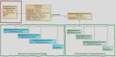
Due to the various supported use cases, the VEC’s concept for component specifications is designed modular. The figure above contains the most relevant elements
Note: The picture is for illustration purpose only and is taken from a current VEC version at the time of writing. The classes, attributes etc. might have changed in the mean time.
The unique identification of a component is its PartVersion. It is serves as an identifier and contains only additional PDM information like Approval,Creation or ChangeDescription. The actual description of the properties of a component is done via PartOrUsageRelatedSpecifications, whereby each specification covers only a certain aspect of the component. A holistic description of a component is a combination of multiple specifications, but no more than one of a specific specification type at a time. Those specifications can be divided into two groups:
General Component Data: Specifications in this group describe general properties of components that are applicable to all or at least a large group of components. For example:
GeneralTechnicalPartSpecificationfor common properties like weight or material for all component types.PlaceableElementSpecificationfor components that have an explicitly defined position in the harness topology lik wire protections, connectors or fixings.LocalGeometrySpecificationfor information about the component’s geometry model, e.g. the bounding box, transformations, segment connection points.
Component Characteristics: Specifications in this group describe properties that are very specific for a certain component type, e.g.
WireSpecificationfor wires orConnectorHousingSpecificationfor connectors. In most cases, a part can be clearly assigned to one of these categories. However, there can be cases of “hybrid” components that fall into more than one category. In this case, thePrimaryPartTypedefines the primary character of the components. A detailed description can be found here: “Description of Parts”.
Unclassified / Custom Component Types
The VEC natively supports a wide range of component types and attributes for them. Nevertheless, this list is probably not exhaustive when considering which component types could potentially appear in the BOM of a wire harness and could also be added by future developments.
Currently, the list of directly supported types is derived from the specific requirements of the VEC and is focused on those components that have a specific relationship with other components in the harness (e.g. wires/connectors) and whose attributes play a strong role in the selection processes during development.
However, following its principle of openness and extendability, the VEC provides a possibility to add such components, that are not specifically supported by it, in a defined way as user/process defined components. The necessary elements to do this are:
- The
PrimaryPartTypeto use isOther. - “General Component Data” can be added with corresponding specifications analogous to a regular component (see above).
- The “Component Characteristics” is expressed by an instance of
PartOrUsageRelatedSpecificationitself (no subclass). - The concrete type of the component (for regular components expressed by the PrimaryPartType), is defined in the
PartOrUsageRelatedSpecification.SpecialPartType-Attribute. - Specific attributes of the “new” type (not available via “General Component Data”) can be added as
CustomPropertyto thePartOrUsageRelatedSpecification. - Instancing is done via a
SpecificRole(see chapter “Instances of undefined Components” in the Specification for Details).
An example in XML of such a custom component can be found in the XML Listings section at the end of this page.
PartMaster - DocumentVersions

A part master document describes the properties of a component or a group of
components (a PartVersion or a set of
PartVersions). It can be recognised with the DocumentType = PartMaster. A schematic illustration can be found in the figure on the right side. It contains some general purpose specifications (highlighted in light blue) and component characteristics (highlighted in strong green), in most cases one. Those specifications are not mandatory and only necessary if the corresponding information aspect is relevant in the use case and can be provided.
Additionally, the document could contain auxillary specifications that are
required for a complete component description (in the illustration the
CavitySpecification and SlotSpecification highlighted in light green).
The emphasis here is on “could”, as this is a quite common case,
but a process-specific interpretation of component definitions. For example, if the cavity system is
described and released together with the connector (in the same document), it
makes sense that the corresponding specification is included in the same
DocumentVersion. However, if the cavity system is defined and released
independently, i.e. in a separate document, and used by multiple connectors, it
would be appropriate to place it in its own DocumentVersion
and reuse the information in the document of the connectors (see Reuse of
Documents).
Content Requirements
In an omniscient view of the world, it would be possible to formulate logical constraints and minimum requirements for the content of a PartMaster-Document, such as mandatory content or a logical relationship between the PrimaryPartType and the types of descriptive specifications that have to be used. For example, it could be stated that each component should have a GeneralTechnicalPartSpecification and one PartOrUsageRelatedSpecification corresponding to its type (e.g. a ConnectorHousingSpecification when the PrimaryPartType = ConnectorHousing).
However, a given VEC file can only be a fragment of this complete picture. The availability of information in a VEC depends on the specific use case, the process, the point in the process, the degree of maturity of the tooling, “need to know” and IP-protection policies and many more. Therefore, even if there are logical constraint, they are not enforced in the VEC.
XML Listings
The listing below contains an example of the general structure of a PartMaster VEC, additionally it does not contain a regular VEC component, but also illustrates the usage of “Custom Component Types”.
<vec:VecContent id="id_00000" xmlns:vec="http://www.prostep.org/ecad-if/2011/vec">
    <VecVersion>2.0.1</VecVersion>
    <GeneratingSystemName>VEC Samples</GeneratingSystemName>
    <DateOfCreation>2022-10-07T00:00:00</DateOfCreation>
    <GeneratingSystemVersion>0.0.1</GeneratingSystemVersion>
    <DocumentVersion id="id_00001">
        <CompanyName>prostep ivip</CompanyName>
        <DocumentNumber>D-213454-143-31</DocumentNumber>
        <DocumentType>PartMaster</DocumentType>
        <DocumentVersion>1</DocumentVersion>
        <ReferencedPart>id_00007</ReferencedPart>
        <Specification xsi:type="vec:GeneralTechnicalPartSpecification" id="id_00002" xmlns:xsi="http://www.w3.org/2001/XMLSchema-instance">
            <Identification>P-213454-143-30</Identification>
            <DescribedPart>id_00007</DescribedPart>
            <ColorInformation id="id_00003">
                <Key>RD</Key>
                <ReferenceSystem>IEC 60757</ReferenceSystem>
            </ColorInformation>
        </Specification>
        <Specification xsi:type="vec:PartOrUsageRelatedSpecification" id="id_00004" xmlns:xsi="http://www.w3.org/2001/XMLSchema-instance">
            <CustomProperty xsi:type="vec:NumericalValueProperty" id="id_00005">
                <PropertyType>power</PropertyType>
                <Value id="id_00006">
                    <UnitComponent>id_00008</UnitComponent>
                    <ValueComponent>1.21</ValueComponent>
                </Value>
            </CustomProperty>
            <Identification>P-213454-143-30</Identification>
            <SpecialPartType>FluxCapacitor</SpecialPartType>
            <DescribedPart>id_00007</DescribedPart>
        </Specification>
    </DocumentVersion>
    <PartVersion id="id_00007">
        <CompanyName>prostep ivip</CompanyName>
        <PartNumber>P-213454-143-30</PartNumber>
        <PartVersion>1</PartVersion>
        <PrimaryPartType>Other</PrimaryPartType>
    </PartVersion>
    <Unit xsi:type="vec:SIUnit" id="id_00008" xmlns:xsi="http://www.w3.org/2001/XMLSchema-instance">
        <SiUnitName>Watt</SiUnitName>
        <SiPrefix>Giga</SiPrefix>
    </Unit>
</vec:VecContent>
Instances of Components
This Implementation Guideline complements the Specification Chapter Instantiation of Components with concrete examples and detailed definitions for specific use cases. Component instantiation in the context of the VEC means the specific usage of a component in a defined function, location or place. Instantiation implies that there is something to be instantiated, which is the type definition. This type definition is often referred to as part master data or component specification. For example a “black connector with 12 pins” is a type definition, where as the “connector of the left head light (black with 12 pins)” is an instance.
The figure below gives a brief overview of how instantiation of components fit into the overall picture of the VEC and how this different for PartOccurrences and PartUsages.

On the left hand side is a part master definition (as described in Component Description). On the right hand side is a DocumentVersion (in this example a HarnessDescription) containing instances of components and additional information.
The two instantiation approaches of the VEC are illustrated with one representative for each. The PartUsage “A120” and the PartOccurrence “A121”. PartUsages and PartOccurrences are defined in different containers (CompositionSpecification vs. PartUsageSpecification). Both can coexist and be used at the same time in the same containing DocumentVersion.
On the far right hand side can be seen, that other areas in the VEC (indicated in orange on the right side) can use these instances regardless of the instantiation concept used.
Relationship to Part Master Data
The information related to a component instance is in the VEC always logically divided in type definition and instance specific properties. In the VEC Type definitions are contained in Specifications, instance specific properties are contained in Roles.
The one major difference between the PartOccurrence and the PartUsage is the way how both are referring to their respective type definition. The PartOccurrence references its part master data specifications indirectly via a PartVersion. It is described by PartOrUsageRelatedSpecifications) and can be reused for multiple PartOccurrences. In contrast to this, PartUsage, references the specifications directly itself without the detour over the PartVersion. The PartUsage can be interpreted as a hybrid of PartVersion and PartOccurrence in a single entity.
One notable difference is, the direction of the relationship with PartOrUsageRelatedSpecifications. The direction for the PartUsage is inverse direction compared to PartVersion. A PartVersion is described by specifications, wheres a PartUsage references the relevant specifications. This has logical reasons in the assumed information lifecycle of the corresponding entities. A PartVersion is a pointer to a “real” component. Over the time, this component can be described with more information (adding specification) without changing the component itself. On the other hand, a PartUsage is defined in place by associating appropriate specifications, those specifications can be created for this individual PartUsage or being reused for multiple PartUsage. Therefore, specification could be referenced over the time by more PartUsages without being changed.
A PartUsage shall reference all PartOrUsageRelatedSpecifications that provide relevant information about itself. This includes general component data and component characteristics that are relevant in the context (compare to “Component Description”). This does not include any specifications that are used transitively by other specifications (e.g. not the ConnectorHousingSpecification that defines the HousingComponent of an EEComponentSpecification, which is used for the PartUsage). This is illustrated in the Figure below (references between Specifications & Roles are omitted).

In the example from the beginning (figure “Comparison of PartUsages and PartOccurrences”), the PartUsage references the specifications from a PartMaster DocumentVersion. However, this approach is not mandatory and the only reason here, is to keep the example as simple as possible. Depending on the context, different approaches to provide a PartUsage with specifications are possible. Reusing existing part master data (as shown in the example) is one. Putting the specifications in an independent DocumentVersion (e.g. a company standard or a type definition) is another one and last but not least, the specifications could also be defined in the same context as the PartUsages.
Instantiation with Roles
PartOccurrences and PartUsages are containing the Roles corresponding to their PartOrUsageRelatedSpecifications (see both figures above, references between the roles & specifications are omitted in the figures for reasons of readability). Directly under PartOccurrence or PartUsage only Roles shall be used, that have PartOrUsageRelatedSpecifications defined directly in the corresponding part master data. Transitive dependencies (e.g. ConnectorHousingSpecification & Role in the figure above) are created in the appropriate subcontext, as defined by the VEC Model.
Following the principle of optionality in the VEC, it is not required to create Roles, for all the PartOrUsageRelatedSpecifications referenced in the part master data, if the corresponding aspect is not relevant in the individual context.
The contained Roles and their referenced PartOrUsageRelatedSpecification do not have to be exactly the same. They can be subset of those, but not a superset.
Shared Specifications
In the example above, the PartUsage and the PartVersion are using the same PartOrUsageRelatedSpecifications. Such a reuse (or sharing) of information pieces is perfectly valid. However, it does not implicate, that the PartUsage is an instance of the PartVersion. The precise meaning is, that in the final product a selected component, which is taking the place of the PartUsage, is required to satisfy the requirements expressed by the referenced specifications. In the example above, those requirements could be satisfied by this particular PartVersion, however, this might not be the only valid choice.
When PartUsages and PartVersions share specifications, this has no deeper meaning than that it is a reuse of a block of information. In particular, the following aspects apply:
The PartUsage is not required to reference all the specifications of the PartVersion. It can even reference contradicting specifications, for example:
- The
PartUsagecould reference only theConnectorHousingSpecification, if the other properties are not a strict requirement. - The
PartUsagecould reference theConnectorHousingSpecificationof thePartVersion, but a differentGeneralTechnicalPartSpecification, if for example the requirements for weight, color or robustness are different.
The PartOrUsageRelatedSpecification for the PartUsage can describe a PartVersion at the same time, but they are not required to. That means, a PartUsage is free to define its own specifications, for example in its own context (DocumentVersion) or in a separate DocumentVersion.
Realization of PartUsages with PartOccurrences
Although PartUsage and PartOccurrence can coexist at the same time (shown in figure 1), they represent different levels of abstraction. The coexistence is only possible, because in reality, a product definition of a harness can contain different layers of abstraction at the same time as well (e.g. some components can be defined in 150% definitions and some are only determinable in a 100% definition).

Figure 2 presents a highly simplified situation for the sake of the concept. On the left hand side is a wiring definition with two Variants, A & B. A & B have the same logical connectivity, however, variant B has a slightly higher power output, resulting in a PartUsage (a requirement!) for variant B with a larger wire cross section area. The wiring also defines the color of the wire. However, other significant properties are left open (e.g. insulation material) for later determination. In the following design process, the other properties required for a component selection are defined (e.g. the insulation material, when the location of the wire in the vehicle is known). It is also decided, that it is more efficient to realize both variants with a single wire (satisfying both requirements at same time). Traceability is preserved in the case, with the RealizedPartUsage reference from PartOccurrence to PartUsage. The fact that a PartOccurrence can realize the requirements of multiple PartUsages at the same time is the reason that the multiplicity of this association is “0..*”.
Selection Tables / Part Substitutions
There are use cases where a specific component cannot be defined at the time of creation for a certain aspect of the product definition. This is often because harnesses are designed as 150% definitions, where some components can only be defined precisely in a 100% definition. Some examples are:
- The selection of a ring terminal depends on the exact number of wires and their cross-sectional area, which can often only be determined in a 100% definition. However, other requirements for the ring terminal (e.g. material, plating, size of the ring etc.) are already known in the 150% definition and can be specified.
- The selection of a tube depends on the exact bundle diameter, which also can often only be determined in a 100% definition. However, other requirements for the tube (e.g. material, color, wall thickness etc.) are already known in the 150% definition and can be specified.
In such cases, it is common practice to define a set or a family of possible components that satisfy the general requirements and can be selected later in the design process, when the other defining characteristics are known. This list of possible components is often referred to as a selection table or part substitution list and is expressed in the VEC by a PartSubstitutionSpecification.
For this implementation guideline, we will use the following selection table:
T-A100 Corrugated Pipe Selection Table
Part Number Description Nominal Size Inner ⌀ Outer ⌀ T-0001 Corrugated Pipe N6/10 N6/10 6.3 mm 10.0 mm T-0002 Corrugated Pipe N9/13 N9/13 9.0 mm 13.6 mm
There are two common ways to represent such a selection table in current design processes:
- Option 1: The selection table is given a regular part number (e.g.
T-A100) and is handled like a regular part. The actual selection of a specific component (e.g.T-0001) is done later in the process by the supplier. The fact thatT-A100is a selection table is only documented in the part drawing or other textual fields. - Option 2: The selection table is not given a regular part number. Instead, it is referenced by a document or drawing number, and the selection table is documented in those textual fields. The actual selection is also done later in the process by the supplier.
Both approaches can be expressed explicitly in the VEC with equal quality. The main difference is that in the first approach the selection table is expressed as a regular PartVersion with a part number, whereas in the second approach it is expressed as a PartUsage without a part number.
First, the items in the selection table must be expressed in the VEC as regular components, each with a PartVersion and all the relevant PartOrUsageRelatedSpecifications. For T-0001 the corresponding XML snippet could look like this:
  ...
  <DocumentVersion id="DocumentVersion_00001">
    <CompanyName>Acme Inc.</CompanyName>
    <DocumentNumber>DOC-T-0001</DocumentNumber>
    <DocumentType>PartMaster</DocumentType>
    <DocumentVersion>1</DocumentVersion>
    <ReferencedPart>PartVersion_00025</ReferencedPart>
    <Specification xsi:type="vec:CorrugatedPipeSpecification" id="CorrugatedPipeSpecification_00002">
      <Identification>CPS-T-0001</Identification>
      <DescribedPart>PartVersion_00025</DescribedPart>
      <InnerDiameter id="NumericalValue_00005">
        <UnitComponent>SIUnit_00028</UnitComponent>
        <ValueComponent>6.3</ValueComponent>
      </InnerDiameter>
      <NominalSize>6/10</NominalSize>
      <OuterDiameter id="NumericalValue_00006">
        <UnitComponent>SIUnit_00028</UnitComponent>
        <ValueComponent>10.0</ValueComponent>
      </OuterDiameter>
      <CorrugationHeight id="NumericalValue_00003">
        <UnitComponent>SIUnit_00028</UnitComponent>
        <ValueComponent>3.0</ValueComponent>
      </CorrugationHeight>
      <CorrugationWidth id="NumericalValue_00004">
        <UnitComponent>SIUnit_00028</UnitComponent>
        <ValueComponent>5.0</ValueComponent>
      </CorrugationWidth>
    </Specification>
  </DocumentVersion>
  ...
  <PartVersion id="PartVersion_00025">
    <CompanyName>Acme Inc.</CompanyName>
    <PartNumber>T-0001</PartNumber>
    <PartVersion>1</PartVersion>
    <PrimaryPartType>CorrugatedPipe</PrimaryPartType>
  </PartVersion>
  ...
Then, the selection table has to be expressed with placeholder component specifications defining the common attributes of the entries in the selection table and a PartSubstitutionSpecification referencing the possible components. The XML for that should look like this:
  ...
  <DocumentVersion id="DocumentVersion_00013">
    <CompanyName>Acme Inc.</CompanyName>
    <DocumentNumber>DOC-T-A100</DocumentNumber>
    <DocumentType>PartMaster</DocumentType>
    <DocumentVersion>1</DocumentVersion>
    <ReferencedPart>PartVersion_00027</ReferencedPart>
    <Specification xsi:type="vec:CorrugatedPipeSpecification" id="CorrugatedPipeSpecification_00014">
      <Identification>CPS-T-A100</Identification>
      <DescribedPart>PartVersion_00027</DescribedPart>
      <CorrugationHeight id="NumericalValue_00015">
        <UnitComponent>SIUnit_00028</UnitComponent>
        <ValueComponent>3.0</ValueComponent>
      </CorrugationHeight>
      <CorrugationWidth id="NumericalValue_00016">
        <UnitComponent>SIUnit_00028</UnitComponent>
        <ValueComponent>5.0</ValueComponent>
      </CorrugationWidth>
    </Specification>
    <Specification xsi:type="vec:PartSubstitutionSpecification" id="PartSubstitutionSpecification_00017">
      <Identification>PSS-T-A100</Identification>
      <DescribedPart>PartVersion_00027</DescribedPart>
      <AlternativePartVersions>PartVersion_00025 PartVersion_00026</AlternativePartVersions>
    </Specification>
  </DocumentVersion>
  ...
  <PartVersion id="PartVersion_00027">
    <CompanyName>Acme Inc.</CompanyName>
    <PartNumber>T-A100</PartNumber>
    <PartVersion>1</PartVersion>
    <PrimaryPartType>CorrugatedPipe</PrimaryPartType>
  </PartVersion>
  ...
PartSubstitutionSpecification and the CorrugatedPipeSpecification reference a PartVersion as DescribedPart. This is only relevant for Option 1, when the selection table is represented as a regular part with a part number. In Option 2, when the selection table is not represented as a regular part, the DescribedPart references of the PartOrUsageRelatedSpecifications and the ReferencedPart of the DocumentVersion can be omitted.The real difference between both options is now, how the selection table is referenced in the actual product definition. In Option 1, the selection table is referenced via its regular PartVersion, by creating a PartOccurrence referencing this PartVersion. The XML snippet for that could look like this:
  ...
    <Specification xsi:type="vec:CompositionSpecification" id="CompositionSpecification_00019">
      <Identification>COMPONENTS</Identification>
      <Component id="PartOccurrence_00020">
        <Identification>TUBE-OCC</Identification>
        <Role xsi:type="vec:CorrugatedPipeRole" id="CorrugatedPipeRole_00021">
          <Identification>TUBE-OCC</Identification>
          <WireProtectionSpecification>CorrugatedPipeSpecification_00014</WireProtectionSpecification>
        </Role>
        <Part>PartVersion_00027</Part>
      </Component>
    </Specification>
  ...
In Option 2, the PartSubstitutionSpecification representing the selection table is referenced directly via the PartUsage. The XML snippet for that could look like this:
  ...
    <Specification xsi:type="vec:PartUsageSpecification" id="PartUsageSpecification_00022">
      <Identification>USAGES</Identification>
      <PartUsage id="PartUsage_00023">
        <Identification>TUBE-PU</Identification>
        <Role xsi:type="vec:CorrugatedPipeRole" id="CorrugatedPipeRole_00024">
          <Identification>TUBE-PU</Identification>
          <WireProtectionSpecification>CorrugatedPipeSpecification_00014</WireProtectionSpecification>
        </Role>
        <PrimaryPartUsageType>CorrugatedPipe</PrimaryPartUsageType>
        <PartOrUsageRelatedSpecification>CorrugatedPipeSpecification_00014 PartSubstitutionSpecification_00017</PartOrUsageRelatedSpecification>
      </PartUsage>
    </Specification>
  ...
The complete example can be downloaded from the Additional Resources at the end of this page.
Composite Parts
Whereas the model description defines the general concepts of multilevel composite parts and 100% and 150% variance for those parts, this implementation guideline follows a use case oriented approach and explains the correct usage of the different aspects of a VEC implementation (e.g. BOM, document structure, variance, instantiation) for different composite part scenarios. The most common ones are defined in the PartStructureContentType open enumeration. The PartStructureSpecification.Content attribute defines, which kind of part, that has a bill of material, is described by a PartStructureSpecification and how the described bill of material has to be interpreted in regard of variance (10%, 100%, 150%).
Assemblies
Assemblies are predefined components, that are typically defined in a central place (e.g. a component library), reused in multiple projects / harnesses and whose inner structure is relevant for the harness design or the development process. Therefore, they are not considered atomic and information about their structure, subcomponents, etc is required. Often, assemblies are defined within their own drawings and have individual part numbers. Examples could be multipart connectors, fixings, grommets or, more complicated, preassembled cables like USB or LVDS.

The figure above illustrates very simplified the concept of an assembly and its usage. On the left hand side you can see the library or part master data definition of the assembly, on the right hand side you can see its usage.
The level of detail for the mapped information of an assembly can range from a pure bill of material view to even a well defined “mini harness”. A pure bill of material view is often not sufficient, especially if the specific usage of the assembly in a larger wiring harness has to be defined precisely (e.g., for preassembled cables the placement of the connectors, the routing of the cable, a.s.o.).
Part Master Data
The following figure “Assembly Definition” illustrates the basic structure of a part master data definition of an assembly. The upper half of the diagram contains the actual definition of the assembly, the lower half (highlighted in blue) contains the definition and details of the utilized subcomponents.

To define an assembly a DocumentVersion is required to contain all necessary Specifications (the “Assembly Definition” highlighted in green). This DocumentVersion has the DocumentType = "PartMaster", just the same as for any other simple component. It can contain any Specification required to describe the assembly (like a GeneralTechnicalPartSpecification).
To describe the inner structure of an assembly, instances of its subcomponents are needed. The instances of the subcomponents can be defined either with PartOccurrences or PartUsages, depending on whether the information about specific parts / part numbers of the subcomponents is required / available, or if the subcomponents are just needed as reference elements to define the concrete usage of the assembly in a harness.
To define the instances of the subcomponents a container specification is required within the DocumentVersion that defines the assembly. This is either a CompositionSpecification or a PartUsageSpecification, depending on the type of instances used for the assembly. In case of the example PartOccurrences are used, and thus a CompositionSpecification is used as container.
CompositionSpecification and the PartUsageSpecification are just used as container to define instances of components. They do not make a statement about the content of an assembly. Not even implicitly by being contained in the DocumentVersion defining the assembly. For this reason, neither the CompositionSpecification nor the PartUsageSpecification is a PartOrUsageRelatedSpecification. This modelling approach enables the VEC to define for example 150% wiring harnesses or assembly families (see later in this implementation guideline).The content of the assembly is defined explicitly with a PartStructureSpecification that references the instances contained in the assembly as InBillOfMaterial and referencing the PartVersion of the assembly as DescribedPart. In other words, the PartStructureSpecification represents the bill of material (BOM) of the assembly (or any other composite part in the VEC). The PartStructureSpecification defines Content="Assembly" and the PartVersion of the assembly has a PrimaryPartType = "PartStructure".
If any information about the subcomponents or their relationships should be defined in a more detailed way (e.g. the contacting of a preassembled cable) appropriate Specifications can be added to the DocumentVersion of the assembly as needed (indicated in the figure with the ContactingSpecification). An assembly can even define its own topology (TopologySpecification) or schematic (ConnectionSpecification).
XML Example
<PartVersion id="id_1001_0">
    <Description id="id_A1" xsi:type="vec:LocalizedString">
        <LanguageCode>En</LanguageCode>
        <Value>Composite Part A1</Value>
    </Description>
    <CompanyName>Example Corp.</CompanyName>
    <PartNumber>N.1</PartNumber>
    <PrimaryPartType>PartStructure</PrimaryPartType>
</PartVersion>
...
<DocumentVersion id="id_1002_0">
    <CompanyName>Example Corp.</CompanyName>
    <DocumentNumber>N.1</DocumentNumber>
    <DocumentType>PartMaster</DocumentType>
    <ReferencedPart>id_1001_0</ReferencedPart>
    <Specification id="id_2000_0" xsi:type="vec:PartStructureSpecification">
        <Identification>P1</Identification>
        <DescribedPart>id_1001_0</DescribedPart>
        <Content>Assembly</Content>
        <InBillOfMaterial>id_2000_2 id_2000_3</InBillOfMaterial>
    </Specification>
    <Specification id="id_2000_1" xsi:type="vec:CompositionSpecification">
        <Identification>C1</Identification>
        <Component id="id_2000_2">
            <Identification>A</Identification>
            <Part>id_1001_1</Part>
            ...
        </Component>
        <Component id="id_2000_3">
            <Identification>B</Identification>
            <Part>id_1001_2</Part>
            ...
        </Component>
    </Specification>
</DocumentVersion>
Usage of an Assembly
An assembly is normally used in a context different from its definition, e.g., the assembly is defined in a master data library and used in a wiring harness. The following figure “Assembly Instantiation” illustrates this scenario.

The instantiation of an assembly is normally done in a separate DocumentVersion (e.g. the definition of a harness, highlighted in purple in the figure above). The assembly itself is instantiated with a PartOccurrence and a PartWithSubComponentsRole, which is the corresponding Role for a PartStructureSpecification. Additionally, all subcomponents (referenced by the PartStructureSpecification) must be instantiated in the using context as well (Component A* & Component B*). By default, those are clones of their part master data definitions. To preserve traceability between occurrences from the part master definition and the occurrences in instantiation context, each instance is referencing its corresponding part master data occurrence as InstantiatedOccurrence. In order to identify their affiliation to a particular assembly instance the PartWithSubComponentsRole references all of them as SubComponent.
At a first glance, this detailed approach may seem partially redundant and superfluous. However, it offers the possibility to redefine properties of the occurrences in the usage and also allows precise definition of the actual usage. Here are some examples:
- Redefinition of identifier and descriptions and associations: Connectors and cores of a predefined cable will have generic names and identifiers in the assembly definition. When used in a vehicle, connectors will fullfil a specific function, so identifiers for connectors will be derived from
UsageNodes; descriptions will be function specific (e.g., “Infotainment USB Port Center Console”) and cores will realize system schematic connections of the vehicle. Furthermore, the same cable could be used multiple times in the same vehicle for different functions. - Redefinition of technical properties: Technical properties of an assembly might change in a specific usage. E.g., a predefined cable (contacted only on one side) comes in a specific length. During the harness assembly it might be cut down to the required length.
- Placement & routing of the assembly in the usage: To define the actual usage, e.g., placement of connectors, routing of wire, a.s.o. occurrences are required. Since an assembly could be used multiple times in different locations and usages in a harness, those occurrences could not be the same occurrences used in the
CompositionSpecificationof part master data definition.
XML representation
The following XML snippet shows the occurrences of the example in the CompositionSpecification.
<Component id="id_2001_2">
    <Identification>Assembly-Instance</Identification>
    <Role xsi:type="vec:PartWithSubComponentsRole" id="pwscr_1">
        <PartStructureSpecification>id_2000_0</PartStructureSpecification>
        <SubComponent>id_2001_3 id_2001_4</SubComponent>
    </Role>
    <Part>id_1001_0</Part>
</Component>

<Component id="id_2001_3" xsi:type="vec:PartOccurrence">
    <Identification>A*</Identification>
    <Role ...>
        ...
    </Role>
    <InstanciatedOccurrence>id_2000_2</InstanciatedOccurrence>
    <Part>id_1001_1</Part>
</Component>

<Component id="id_2001_4" xsi:type="vec:PartOccurrence">
    <Identification>B*</Identification>
    <Role ...>
        ...
    </Role>
    <InstanciatedOccurrence>id_2000_3</InstanciatedOccurrence>
    <Part>id_1001_2</Part>
</Component>
Harness & Modules
From a high level perspective, a harness is just a “very complicated” assembly. The two major differences are:
- a harness is designed with variance in mind. In most cases it is a 150% definition containing either modules for a customer specific harness or a set of predefined variants.
- It is designed for a very specific use case (e.g., a vehicle) and its reuse in the process is very limited, in contrast to an assembly.

The figure above illustrates the concept of a harness in a very simplified way. A harness definition has several layers. The base layer consists of a set of component instances and their relationships, for example connectors, wires, terminals or even assemblies. The component instances in the base layer are used to define the function / appearance of the harness (e.g., contacting and routing of wires, placement of components) in all possible variants (150%). The other layers are used to manage the variance and to achieve a configurable product. The concepts (and the names) in these layers sometimes differ slightly in the various processes. However, from a data structural point of view, those differences are marginal.
For a customer specific harness, the next level defines Modules. A module represents a handle for a specific subset of component instances in a 150% harness. The strategies for modularization of a harness are manifold and quite process specific, but they are always influenced by the variant structure and the logistic concept of the product. However, modules do have in common, that they just represent a set of components that should be controlled individually in the configurable product. In this respect, modules are logistical units rather than real parts. A module itself is normally free of variance and does not represent a functional subset on its own, in other words, it is just a 10% set of components and not 100%. This means that only the correct combination of multiple modules creates a functional harness that can be found in a actual vehicle. The harness definition itself consists of all modules (150%). For a specific vehicle configuration, a subset of all modules is picked. The combination of those modules creates a specific variant (100%).
Not all harnesses are designed as customer specific harnesses. For less complex harnesses (e.g., the doors) or for the sake of a simpler order and manufacturing logistic, a set of preconfigured harness variants1 is often used. Two approaches exist for this:
- In the first approach the variants are defined as a set of components (“Variant X” in the figure, the dashed arrow stands for the references to all components required for “Variant X”). So they are basically defined in the same way as a module, with the difference that each variant represents an actual harness (100%) by itself.
- In the second approach, the components are grouped into modules (in this context often named “options”), just as with the customer specific harness. The specific harness variants are then defined as subsets of the modules / options (“Variant Y” in the figure).
Details
The following figure shows the basic structure of a harness definition in the VEC. It has to be read from left to right.

The harness definition starts on the left hand side with the COMPONENTS CompositionSpecification. It contains all component occurrences that are required for the harness (or its definition). If the harness contains components without a specific PartVersion, the use of PartUsages is also valid. The illustration contains only the hierarchical structure of a harness definition. A complete definition will include a wide variety of additional Specifications that allow the detailed definition of the harness based on the occurrences (e.g. TopologySpecification, PlacementSpecification, RoutingSpecification, ContactingSpecification).
Based on these part occurrences, each module (Module A & Module B) has a PartStructureSpecification (highlighted in yellow), that describes its PartVersion. This is completely analogous to the representation of assemblies. However, a harness (or a variant) is not created with Module PartVersions but with PartOccurrences of modules. For a clear structuring of the containments in VEC document the module occurrences (highlighted in orange) are placed in a second CompositionSpecification, the MODULES in the middle of the illustration. Each module’s PartOccurrence has a PartWithSubComponentsRole, just as described above to the assembly instancing. However, due to the special nature of modules in a harness definition, the PartWithSubComponentsRole does not reference a cloned set of PartOccurrences, but the same that are used for PartStructureSpecification. All PartOccurrences referenced by the corresponding PartStructureSpecification as InBillOfMaterial must also be referenced as SubComponent by the PartWithSubComponentsRole. This supposed redundancy is due to the fact that a module is in principle defined by its first (and often only) occurrence. Although redundant, it is intentionally required to fill both associations (PartStructureSpecification -> PartOccurrence & PartWithSubComponentsRole -> PartOccurrence). This unifies the handling of assemblies and modules for reading systems.
Finally (on the right side), the harness (150%) or a specific variant (100%) is defined as “bill of modules” with a PartStructureSpecification referencing all module occurrences that belong to the harness.
Even if this represention of a harness in the VEC appears to be somewhat more extensive at the first glance than, for example, in the KBL, it does have some advantages:
- The VEC has a general concept for a multilevel bill of material with support of variance. The number of levels (components, assemblies, modules, harness) is arbitrary. It is also possible to create an orthogonal structuring, e.g., for production BOMs vs. logistic BOMs.
- The
PartOccurrenceseparates context specific information (e.g,. variant configurations) from part master data. If a harness is reused and a module has different context information (e.g. different variant configurations in different vehicles) then, this is possible without recreating a module. - Reusing shared modules in different harnesses is, with slight changes for the reusing context, also supported.
Stufenkabelbaum ↩︎
Coupling
The VEC interprets the term “coupling” to encompass various types of plug-in or detachable connections within the wiring system. This includes the linking of wiring harnesses with one another, wiring harnesses with E/E components, and E/E components with one another (for example, fuses within fuse carriers). A distinction must be made between two dimensions: on the one hand, the definition in the master data of the components for valid combinations and the mapping of the different sides (see Cavity Mapping), and on the other hand the definition of a coupling in the actual use (see Coupling Specification). This is indicated in the figure below on the left hand side for the part master data and on the right hand side for the harness definition.

Aspects of the Coupling
From a conceptual point of view, the properties of a pluggable connection can be separated into two aspects, mechanical properties like which connectors fit each other or which cavities are opposite each other and electrical properties like which pin is connected to which terminal / wire. Since those information can be defined in different domains and different point in the development process, the VEC allows the definition and exchange of these aspects independant from each other. This is illustrated by the exemplary process below.

The following activities are hidden behind the process steps shown.
- Abstract Wiring Definition: Electrical connections (“proto wires”) are connected to logical pins of an E/E component (see Wiring). In terms from above, the definition of the eletrical aspect of the coupling in its usage is required.
- ECU Interface Definition: The mechanical interface of the E/E component (“the Header”) is assigned. A mapping between electrical pins of the E/E component and the cavities of the ECU connector is created. This is done in the part master data of the E/E component.
- Harness Connector Selection: A harness connnector that is compabtible to E/E component connector is selected. This is done taking into account the mechanical properties of the connector. Normally, other criteria are also taken into account here, such as the properties of the installation space or compatibility with terminals. However, foundation for this are the mechanical properties of a connector defined in den part master data.
- Cavity Assignment Harness Connector: Based an on a mapping between E/E component connector cavities and harness connector cavities, defined in the part master data, it can be calculated which cavities in the usage are opposite to each other. As it is known which Pin is associated to which E/E component connector cavity and it is also known which harness terminal / wire is associated to which E/E component pin, the accociation between harness connector cavity and harness terminal / wire can be derived.
Following the paradigm of the VEC, both the input data and the results of the steps just described can be represented in the model and used independently of each other. The concepts for each step are described in the sections below (following the order from above).
Electrical Coupling
The electrical aspects of a coupling in concrete usage are defined with a MatingPoint and MatingDetails in the case terminals with multiple TerminalReceptions (see figure “Electrical Coupling” below).
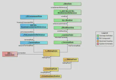
There are situations, where logical Connections are realized in physical layer directly by a pluggable “connection” (e.g. two E/E components are conntected directly to each other, see Direct Connectivity). Therefore, the MatingPoint can create traceability links into the schematic layer.
The CouplingPoint is used to group the information that is associated with a single coupling operation (e.g. all connections that are created with the plugging of a single connector). If this grouping is already known in the electrologic layer, it is useful (e.g. for traceability reasons) to group the MatingPoints in a CouplingPoint. However, if this is not know at the time of creation, it is perfectly valid to create an individual CouplingPoint for each mating. Nevertheless, when these ungrouped matings are assigned to a connector at a later stage, they shall be regrouped und a single CouplingPoint.
E/E Component Interface Definition
The assignment of electrical pins in an E/E-component to cavities of the mechanical interface is described in detail in the guideline about E/E-components.
Mechanical Compatibility and Mapping of Connectors
Coupling compatibility in the part master data is defined with a Mapping within a MappingSpecification. Due to the distributed nature of part master data the mapping is not defined with explicit reference, but by defining pairs of keys (e.g. CavityNumber). This is illustrated in the figure below. As you can see, the Mapping only requires links the PartVersions. Apart from that, it is self-contained and independant from the part master data definition. Therefore, it can be exchanged idenpendantly without then to embedd all ConnectorHousingSpecifications of the related connectors.
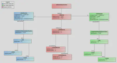
The semantic of the mapping is, that it describes a mapping for the ConnectorHousingSpecification “related” to the PartVersions, but what does “related” mean? Currently there are two PrimaryPartTypes that utilize the ConnectorHousingSpecification, ConnectorHousing and EEComponent.
For a ConnectorHousing “related” is defined as the ConnectorHousingSpecification that are referencing the PartVersion as describedPart. Usally this is just one. For an EEComponent “related” are the ConnectorHousingSpecifications that are used to by the HousingComponents of the EEComponent. This can be as many as there are HousingComponents. To resolve this ambiguity, the IdentificationA & IdentificationB relate to the Identification of the ConnectorHousingSpecification upon which the mapping is defined.
These properties (IdentificationA & IdentificationB in the Mapping) are optional for backwards compatibility, because they where first introduced in VEC 2.1. In versions before, there was chance to have an ambigious mapping for E/E components. See next section for an explanation.
ConnectorHousingSpecifications in the Mapping, for data created with VEC 2.1 and later.Ambiguity of the Mapping (before V2.1)
The diagram below shows the situation for mappings before VEC V2.1. On the right side it is pretty clear, which slot is adressed SlotMapping.IdentificationB = 1, since the PartVersion 6789 is a “ConnectorHousing” and has only related ConnectorHousingSpecification. On the left hand side, this is only the case, because of the special situation illustrated in the diagram, where the ConnectorHousingSpecification “I” and “II” define different values for Slot.SlotNumber, which are unique within the scope of the E/E component.
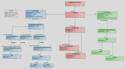
But, in general the SlotNumber is only required “to be unique within a ConnectorHousingSpecification”. So it would be perfectly valid for an E/E component to use ConnectorHousingSpecifications that define Slots with identical SlotNumbers like “A”, “1”, “default” or whatever else the specific naming convention of the process defines as appropriate. However, in this case it would not be possible to associate defined mapping with the correct ConnectorHousingSpecification.
Therefore, VEC V2.1 introduced corresponding “IdenticationA” & “IdenticationB” attributes in the Mapping (see diagram below). Despite having the same SlotNumbers un the right side, the mapping is defined unambigiously.
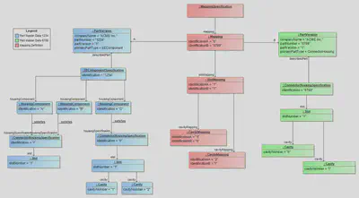
For backwards compatibility it is allowed to omit the Identification-attributes in the Mapping, but this is only permitted in cases where the mapping still can be associated unambigiously, even without the Identifications in the Mapping-class. This is normally the case for regular ConnectorHousing, which only a single related ConnectorHousingSpecification and EEComponents that satisfy the requirement of unique SlotNumbers within all ConnectorHousingSpecifications related to EECompionent (as illustrated in figure “Ambigious Mapping before VEC V2.1”).
To simplify the situation for future implementations, it is highly recommended to define the Identification-attributes in VEC V2.1 and later, even if they are not mandatory.
The only solution to define an unambigious mapping for situations like the one illustrated in figure “Unambigious Mapping for VEC V2.1 and later” in VEC versions before 2.1, is to define CustomPropertys for IdentificationA & B on the extendable Mapping-class.
Mechanical Coupling
As described in section Aspects of the Coupling the mechanical coupling in a specific usage can be derived from the part master data and the Mapping. The result of that process is stored in the “mechanical” part of the CouplingPoint. However, this derivation process is not necessarily required. As always, the VEC makes no assumption about the creation process of a specific information item, e.g. if the process requires a manual definition in the usage, this would be perfectly valid as well and the result of the process would stored in the CouplingSpecification.
It would also be imaginable to have a process where the definition of the coupling for a bordnet would happen after the development of all involved harnesses. In this case, the CouplingSpecification might be created in its own DocumentVersion.
The figure below contains an example of a completely defined CouplingPoint.
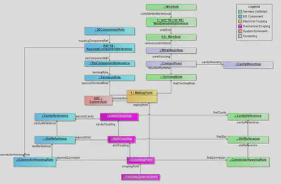
Harness (KBL/VEC Mapping)
Disclaimer: This page or section is currently under review by the community.
The content of this page or section can be subject to change at any time. If you find any issues or if you have any review comments please drop us an issue in our Issue Management on GitHub.
Editorial Note: Since the creation of this implementation guideline will span an extended period, the current work-in-progress versions will be published continuously to allow the community to review and provide feedback.
This implementation guideline outlines the core concepts needed to create a dataset for a single wiring harness in the VEC, which is also the use case that lies in the center of the scope of the KBL.
To ease adoption for those already familiar with the KBL, this guideline is structured as a mapping from the KBL model to the VEC model. Additionally, a reference implementation of a KBL-to-VEC converter is available on GitHub.
Disclaimer: This implementation guideline (along with the converter implementation) covers only the scope of the KBL. The VEC is a far more expressive model.
As a result, there are scenarios where the VEC could convey information with much clearer semantics. However, the necessary data for this level of precision is often not available in the KBL (e.g., detailed component data) or is embedded through custom properties and process/tool-specific dialects. “Healing” such data would require in-depth knowledge of the specific KBL dialect used and, in many cases, the integration of additional information sources (side-loading). This task lies outside the scope of this guideline. In situations where it is obvious that fixing of such deficiencies is advised, a Data Quality note is added.
The goal of this guideline is to demonstrate how standard KBL concepts map to VEC concepts—without improving the quality of the underlying information. While the VEC could indeed express many aspects more precisely, this guideline focuses on maintaining consistency with the original KBL data quality.
There are fundamentally two approaches to describing such a mapping. One can either start from the source model, explaining how its information is distributed into the target model, or take the opposite approach by defining which information is needed in the target model and where to find it in the source model. For this implementation guideline, the latter approach was chosen as the strategy.
On the one hand, the guideline’s focus is on how to describe a harness in the VEC, which naturally suggests describing the mapping from this perspective. On the other hand, the VEC is the more precise model, meaning that many KBL concepts are distributed across different elements within the VEC. For example, a KBL Node contains information relevant to the VEC concepts of a TopologyNode , GeometryNode2D and GeometryNode3D. It is more logical to describe the mapping of topology and 2D/3D geometry as cohesive units rather than addressing all three concepts in a mixed manner starting from the KBL Node.
The implementation guideline focuses on the structural mapping and does not cover the mapping of individual attributes. If you are interested in those details, please refer to the reference implementation.
The guideline follows a logical order rather than an order dictated by model dependencies. Since the VEC is a graph—not a strict tree—it allows cross-references between branches. As a result, you may encounter cases where a model element references another model element whose mapping is described later in this guideline.
The reference implementation addresses this challenge by using a two-phase approach.
Starting Point
Everything starts with the model root element VecContent, see the figure below (all attributes omitted).
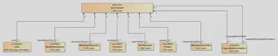
The following sub elements of the VEC are required for a harness description and are covered by some information in the KBL (the sections containing the detail information are linked):
PartVersions
The concept of parts is quite different in KBL and VEC. In the VEC a PartVersion is just a PDM-Header for the part. The various aspects of a part (e.g. is it a wire or connector) are handled by different types of PartOrUsageRelatedSpecifications contained in the DocumentVersion describing the part. In the KBL, the different types of parts are expressed as subclasses of Part. The concept in the VEC that most closely reflects the approach of the KBL is the PrimaryPartType.
PrimaryPartType is merely a preliminary “best guess” approach. In many cases, the “standard” KBL provides only a very general classification, whereas the VEC allows for more specific distinctions. For example, the KBL only recognizes Wire_protection, while the VEC differentiates between TubeSpecification, TapeSpecification, and others.The following PrimaryPartType could be used for KBL Parts:
| KBL Class | VEC PrimaryPartType |
|---|---|
| Accessory | Other |
| Co_pack_part | Other |
| Cavity_plug | CavityPlug |
| Cavity_seal | CavitySeal |
| General_wire | Wire |
| Connector_housing | ConnectorHousing |
| Fixing | Fixing |
| General_terminal | Terminal |
| Wire_protection | WireProtection |
| Harness | PartStructure |
| Harness_configuration | PartStructure |
| Module | PartStructure |
| Assembly_part | PartStructure |
| Fuse | Fuse |
| Component_box | EEComponent |
| Component | EEComponent |
When mapping into the VEC, a PartVersion Object is required for each KBL Part. Those can be found under /KBL_container/(Accessory|AssemblyPart|CavityPlug|...), /KBL_container/Harness/Module and /KBL_container/Harness/Harness_configuration.
Data Quality: The KBL allows to have the same Part_number under different classifications. E.g. a tape can be used as Wire_protection or as Accessory to some other part (see Part for more details).
Due to other modeling approaches in the VEC, there is no longer any need for this. Multiple occurrences of the same part version in the VEC are considered a semantic error. Deduplication should be carried out in post-processing.
DocumentVersions
In the VEC, all payload data is contained within DocumentVersions. Typically, you would structure those according to the actual documents used in the process. Unfortunately, this concept in its detail form is not present in the KBL. Therefore, for the generic conversion described here, practical assumptions need to be made:
- It is common practice to describe components in individual datasets/documents and publish them separately → one
DocumentVersionfor each harness component (e.g. connector, wire and terminal, see Partitioning and Sizing), see section Part Master Data. - It is also common for a wiring harness to be fully described in a single 150% dataset, containing all information about the used component occurrences, variants, connectivity, dimensioning, and so on → one
DocumentVersionfor the harness itself, see section Harness Description.
This means that a DocumentVersions with DocumentType=PartMaster must be created for each component used in the wiring harness. These are all instances of Part in the KBL except instances of Part_with_title_block.
For the Harness itself, a DocumentVersion with DocumentType=HarnessDescription is created. This document contains all relevant information about the harness as well as the Specifications for the Modules and Harness_configurations.
Part Master Data
For all components used in a wiring harness, a minimum set of part master data is required.
A PartMaster document contains all PartOrUsageRelatedSpecifications that are required to describe the component. For a general description of this concept see the Guideline “Component Description”. The following specifications have to be created. The Mapping of those is described in the section Specifications:
The following table defines the PartOrUsageRelatedSpecification that are used to define each Part. Auxiliary specifications that might required by the PartOrUsageRelatedSpecification for a complete definition (e.g. WireReceptionSpecification, CavitySpecification or InsulationSpecification) are listed in the corresponding section.
Harness Description
A HarnessDescription document contains all Specifications that are required to describe a Harness. The specifications in the VEC provide a more “view oriented” modelling approach than the KBL. Each specification representing a specific view on the product model, with the possibility to have links between the views. The following sections will describe the mapping topic by topic (or, in other words view by view).
A VEC derived from a single KBL contains one HarnessDescription document for the Harness defined in the KBL.
Bill of Material / Part Structure
One central view on the product is the bill of material (BoM) or part structure. The information which parts (components) are used for the harness, its variants and modules.
The KBL has a very explicit definition of the part structure with predefined levels and semantics, compare the diagram below (Note: The diagram is, for the sake of simplicity, conceptually, and not precisely KBL syntax):
- Harness: The container for all variants and part occurrences that compose a harness description (150% definition).
- Module: A subset of part occurrences the is used for variant management within the harness (< 100%).
- Harness_configuration: A set of Modules used to define specific variants of a harness (= 100%)
- Module_configuration: A subset of part occurrences without part number (< 100%).
- Assembly_part: A predefined part consisting of multiple parts, that is used within a harness (e.g. a USB-Cable).
- Connection_or_occurrence: An occurrence (usage) of a part/component within the harness with capability to define usage specific information (e.g. wire length).
In contrast, the VEC provides a highly generic and flexible concept for representing Bills of Material (BoMs). While a strictly defined and semantically precise model, like the one in KBL, has clear advantages — such as unambiguous interpretation and validation — it must also be capable of reflecting real-world complexity. The rigid semantics of the KBL work well within its original scope, but become increasingly insufficient when moving beyond it.
In broader application scenarios, additional concepts are often required, such as production modules, lead sets, or vehicle configurations e.g. for cost and variant calculations. Furthermore, the interpretation of certain concepts may vary depending on the stakeholder’s perspective. For example, an OEM might define a structure as an assembly, whereas a Tier1-supplier may regard the same structure as a module. This highlights the need for more adaptable and context-aware modeling approaches, as supported by the VEC. The basic concepts are illustrated in the following diagram:
The CompositionSpecification serves as a container for defining PartOccurrences. At this stage, it is not yet associated with any specific part and does not represent a configuration of parts. Such an independent container is necessary, particularly when describing variant-rich (150%) products, where individual occurrences of parts cannot always be uniquely assigned to a single configuration unit and may be reused in multiple contexts (150% definition).
Using the PartStructureSpecification, subsets of the previously defined PartOccurrences can now be selected and defined as the Bill of Material (BoM) for a specific PartVersion. These PartVersions can, in turn, be instantiated as PartOccurrences to define another level of the BoM.
This recursive structure allows for the representation of hierarchical BoMs of arbitrary depth, as well as parallel BoM structures—for example, engineering BoM (EBOM) and manufacturing BoM (MBOM).
The assignment to semantics commonly used in harness development (such as harness, module, etc.) is done via the content attribute of the PartStructureSpecification with literals defined in PartStructureContentType. This classification then implies semantic constraints — for example, with respect to completeness (e.g. 100%, 150%) and the types of elements that are allowed.
A typical example: a variant usually consists of modules, which means that only PartOccurrences representing modules may be referenced in a variant’s BoM.
As shown in the diagram above, the Bill of Materials (BoM) structure in KBL essentially consists of three levels:
Harness / Harness_configuration: This represents the top level of the hierarchical BoM. The interpretation of the Harness element varies depending on whether the context is a staged wiring harness (Stufenleitungssatz) or a customer-specific harness (KSK):
- In the case of a KSK, the Harness represents a 150% BoM of all orderable modules. Existing Harness_configuration elements are orthogonal to this and typically represent predefined variants, e.g., for calculation purposes.
- For staged harnesses, the Harness element merely serves as a container for defining the various variants, which are modeled as Harness_configuration elements.
Modules: Break down the complete set of all occurrences (150%) into smaller subsets suitable for variant management.
Connection_or_occurrence: All instances of the harness components (e.g. connectors, wires)
The basic mapping of those concepts into the generic approach of the VEC is illustrated in the diagram below.
Each layer consists of a part master definition (PartVersion), that is used to create instances (PartOccurrence) within a container for the layer (CompositionSpecification). For the sake of a modular data structure, each layer defines its own CompositionSpecification. The PartOccurrence of one layer are then used to define the part master definition of the next layer (PartStructureSpecification and PartVersion).
A detail not shown in the diagram above is that an instance of a BoM part must include references to its subcomponents. In the case of library parts (i.e., Assembly_part in KBL), the subcomponents are represented by distinct PartOccurrence instances, separate from those used to define the part’s structure.
In contrast, for modules within a wiring harness, the same PartOccurrence instances are reused, both to define the structure and for instantiation. This distinction reflects different instantiation approaches and has important implications for reuse and traceability. A detailed explanation of these modeling approaches can be found in the VEC specification under: Instantiation Approaches
Mapping KBL Classification to PartStructureContentType
The following table defines the Mapping between KBL classifications and PartStructureContentTypes.
| KBL Classification | PartStructureContentType |
|---|---|
| Harness | Harness |
| Harness_configuration | Variant |
| Module | Module |
| Assembly_part | Assembly |
XML Representation
The following XML listings explain the BoM mapping in detail. They start from the lowest level (the components) and the end at the top (the harness).
The first step is to create the basic occurrences for the harness. For every Connection_or_occurrence in the KBL Harness a PartOccurrence is created. An exception is the KBL Connection, which is not representing an occurrence of a component, and therefore no PartOccurrence is created in the VEC. The Roles are omitted in the snippet below, as this a separate topic, handled in Instantiation of Components. The Identification used for the CompositionSpecification is COMPONENTS.
    <Specification xsi:type="vec:CompositionSpecification" id="CompositionSpecification_00289">
      <Identification>COMPONENTS</Identification>
      <Component id="PartOccurrence_00290">
        <Identification>GenericIdentifier-0</Identification>
        <Part>PartVersion_00375</Part>
        ...
      </Component>
      <Component id="PartOccurrence_00291">
        <Identification>GenericIdentifier-1</Identification>
        <Part>PartVersion_00375</Part>
        ...
      </Component>
      ...
    </Specification>
For each module, a PartStructureSpecification is created, referencing the occurrences that belong to the module, defined above.
    <Specification xsi:type="vec:PartStructureSpecification" id="PartStructureSpecification_00368">
      <Identification>PSS-MDL123456</Identification>
      <DescribedPart>PartVersion_00504</DescribedPart>
      <Content>Module</Content>
      <InBillOfMaterial>PartOccurrence_00291 PartOccurrence_00290 ...</InBillOfMaterial>
    </Specification>
To define the next layer, instances of the modules are required. Those are created within a separate CompositionSpecification with the Identification = 'MODULES'. As it can be seen, the module PartOccurrence references the same component PartOccurrence as the PartStructureSpecification. This is, because modules are normally defined in-place (see Instantiation Approaches). However, to provide a consistent appearance in the model for all parts with a BoM, both concepts shall be used.
    <Specification xsi:type="vec:CompositionSpecification" id="CompositionSpecification_00286">
      <Identification>MODULES</Identification>
      <Component id="PartOccurrence_00287">
        <Identification>MDL123456</Identification>
        <Role xsi:type="vec:PartWithSubComponentsRole" id="PartWithSubComponentsRole_00288">
          <Identification>MDL123456</Identification>
          <PartStructureSpecification>PartStructureSpecification_00368</PartStructureSpecification>
          <SubComponent>PartOccurrence_00291 PartOccurrence_00290 ...</SubComponent>
        </Role>
        <Part>PartVersion_00504</Part>
      </Component>
    </Specification>
As a Module is now a regular PartOccurrence the generic concepts in the VEC for PartOccurrences can now be applied (e.g. Variant Management, see below) and no module specific modelling concepts, like the KBL Logistic_control_information are required.
Based on the module PartOccurrences, now a PartStructureSpecification for the harness can be defined.
    <Specification xsi:type="vec:PartStructureSpecification" id="PartStructureSpecification_00367">
      <Identification>PSS-LTG0011200</Identification>
      <DescribedPart>PartVersion_00500</DescribedPart>
      <InBillOfMaterial>PartOccurrence_00287 ...</InBillOfMaterial>
    </Specification>
Instantiation of Components
Variant Management (Logistic Control Information)
The KBL uses the Module_configuration element and its Logistic_control_information attribute to define variant management information. In contrast, the VEC offers a more flexible approach, allowing variant management data to be associated with almost any element that is a subclass of ConfigurableElement. Additionally, the VEC introduces an indirection layer, enabling elements to be supplemented with variant management information either retrospectively or externally. It is also possible to assign different control information to an element depending on the context.
As a result, the single Logistic_control_information attribute in the KBL is mapped to a more comprehensive set of classes and attributes in the VEC, providing greater flexibility and specificity in variant management. Specifically, two specifications are required for this purpose, with one instance of each per harness:
- The
VariantConfigurationSpecificationdefines the set of configuration terms used. For each distinctLogistic_control_informationstring, a correspondingVariantConfigurationshould be created. - The
ConfigurationConstraintSpecificationassigns these terms to specific elements. For each Module with aLogistic_control_information, aConfigurationConstraintshould be created to link the correspondingPartOccurrenceto the appropriateVariantConfiguration.
The following XML snippet illustrates the required specifications and their relationships.
    <Specification xsi:type="vec:VariantConfigurationSpecification" id="VariantConfigurationSpecification_00403">
      <Identification>VCS-LTG0011200</Identification>
      <VariantConfiguration id="VariantConfiguration_00404">
        <Identification>VarConf_MDL123456</Identification>
        <LogisticControlExpression>L0L+ALL</LogisticControlExpression>
        <ConfigurationType>Logistic</ConfigurationType>
      </VariantConfiguration>
    </Specification>
    <Specification xsi:type="vec:ConfigurationConstraintSpecification" id="ConfigurationConstraintSpecification_00405">
      <Identification>CCS-LTG0011200</Identification>
      <ConfigurationConstraint id="ConfigurationConstraint_00406">
        <Identification>ConfConstraint_MDL123456</Identification>
        <ConfigInfo>VariantConfiguration_00404</ConfigInfo>
        <ConstrainedElements>PartOccurrence_00408</ConstrainedElements>
      </ConfigurationConstraint>
    </Specification>
    <Specification xsi:type="vec:CompositionSpecification" id="CompositionSpecification_00407">
      <Identification>MODULES</Identification>
      <Component id="PartOccurrence_00408">
        <Identification>MDL123456</Identification>
        <Role xsi:type="vec:PartWithSubComponentsRole" id="PartWithSubComponentsRole_00409">
          <Identification>MDL123456</Identification>
          <PartStructureSpecification>PartStructureSpecification_00589</PartStructureSpecification>
          <SubComponent>...</SubComponent>
        </Role>
        <Part>PartVersion_00725</Part>
      </Component>
    </Specification>
PartStructureSpecification) and in its instance/usage aspects (i.e. PartOccurrence). The variant management is always attached to usage context of something. Therefore, the ConfigurationConstraint is pointing to the PartOccurrence.Topology
Specifications
GeneralTechnicalPartSpecification
ConnectorHousingSpecification
TopologySpecification
CompositionSpecification
Modules describe the dual character of modules (occurrence & part).
PartOccurrences
Identification is mandatory… not all KBL Occurrences have mandatory identification.
Core Elements
Custom Properties / Installation Information
KBL Installation Information not always used as custom property.
String / LocalizedStrings
NumericalValue
Units
To define numerical values, both the VEC and the KBL require units. If the attributes Si_unit_name, Si_prefix, and Si_dimension have been used to define a KBL Unit, it can be mapped straight forward to a SIUnit in the VEC.
Unit_name. When translating this into the VEC, those units can only be mapped to a VEC CustomUnit.Description of Components Types
This section deals with the peculiarities of specific types of components. The structure of the specification is mainly organized according to the different layers and abstraction levels in the model. As a result, the aspects for a holistic view of a particular component are divided into the areas General Component Data, Component Characteristics and Instances of Components in the specification. The implementation guidelines in this section provide an orthogonal view on this, trying to cover all aspects (master data, instancing etc.) for a specific component type.
For a general description of master data definition and instancing concepts of components, see Component Definition & Instantiation.
Wires
This Implementation Guideline covers the various aspects of a correct wire representation in the VEC for different scenarios and variants of wires. It covers both multi cores and single cores.
The VEC contains model elements for the representation of wires which would not be strictly necessary for the exclusive representation of single core wires. However, single core wire elements with the same specification can occur in both, single and multi-core wires. In order to achieve a consistent representation of all cases in the model and in order to allow the reuse of data elements, a uniform modelling approach was chosen for single and multicore wires. At the first glance, this may seem unnecessarily complicated in the case of single core wires, but it simplifies the mapping of wires in the VEC on the long run, when all kinds of wires and not only single-cores have to be supported.
Specifying the Elements of a Wire
In the world of the VEC, a wire is a hierarchical structure of WireElements. A wire element can be any node in the hierarchy that has to be addressed individually for the definition of specific properties. A wire element can be manifested either by physical material (e.g. a core, an insulation, a shield) or by the logical necessity for the definition of certain product properties during the production process (e.g. a grouping for twisted pairs).
The properties of WireElement are defined with a WireElementSpecification (see the figure below).

The WireElementSpecification is a generic, reusable definition of the properties of a wire element. That means, multiple WireElements can reference the same WireElementSpecification, if they share the same technical properties. A specified wire element can be used in different contexts. For example, a white single core can be used as individual single core wire or as part of several different multi core wires. It can even be used multiple times as part of the same multi core (compare CAT7 twisted pair cables that might contain up to 4 similar white cores). Therefore, the definition is represented by a WireElementSpecification, which is independent of a specific WireSpecification.
The actual technical properties of a wire element are defined by referencing a corresponding auxiliary specifications. For example (see the Diagram Wire in the recommendation for a complete list):
InsulationSpecificationif the wire element has insulation properties, and/orConductorSpecificationif the wire element has conducting properties.
WireElementSpecification was also used to define the hierarchical structure of a wire. However, this approach turned out to insufficient for an unambiguous representation of complex wires (see next section for details). Therefore, since VEC version 2.2.0 the hierarchical structure of a wire is defined by the WireElements only and the use of WireElementSpecification.SubWireElementSpecification is discouraged.WireElementSpecification. For example, in the real world all FLRY wires with a specific cross section area have the same properties for the core. This can (not a must) be expressed in the VEC by sharing the same CoreSpecification.From the individual Elements to a whole Wire
From a part master data perspective, the WireElementSpecification was (pre VEC V2.2) sufficient to describe a wire with all its aspects, when navigating from the root wire element to its leaves. However, the ability to reuse WireElementSpecifications within a {{ vec-class WireSpecification }} or between multiple wires introduced a draw back:
Referencing a
WireElementSpecificationdoes not unambiguously define which wire element is actually meant in the context of its usage.
The following figure shall illustrate this. The red lines are hypothetical associations for the demonstration of the problem. In the VEC those associations do not exist, because of the described problem the actual model is different.
When navigating from a part master data perspective (e.g. PartVersion A → Composite-Wire B → White-Core) the context is unambiguously defined by the navigation path. However, in the model the part master data is normally used somewhere, for example the wire is used somewhere in the harness. This is indicated by the RoutedWire in the figure. In that case, it is vital to know which wire element in which wire is actually meant. However, when doing a reverse navigation in the model, indicated by the red lines, it is not clear which white core is actually meant. The white core is reused in multiple wires (or in multiple locations within the same wire). Therefore, the context is ambiguous.

To solve this dilemma, the VEC introduced the WireSpecification and the WireElement. The WireSpecification is the PartOrUsageRelatedSpecification of a wire and the mandatory root of any wire (element) that can be used as an individual component. It references the root WireElement and the root WireElementSpecification (deprecated since VEC V2.2).
The WireElement is the context specific handle of a WireElementSpecification in a specific WireSpecification (primarily needed for multi cores, but due to a consistent modelling approach also mandatory for single cores). The WireElement also defines the actual hierarchy of the wire elements within the wire. The WireElements are used as a target for references.
WireElementSpecification and WireElements has been deprecated with VEC V2.2, because for a precise definition of the hierarchy the WireElementSpecification.SubWireElementSpecification was insufficient and incomplete, especially when using the same specification multiple times. Therefore, this association was deprecated and the reuse of complex structures among multiple wires is not supported anymore. However, the hierarchical structure of a wire is now unambiguously defined by the WireElements only.Definition of a Single Core

The figure above illustrates the representation of a single core wire in the VEC. The WireSpecification is the PartOrUsageRelatedSpecification describing a PartVersion. Each WireSpecification has a single root WireElement that serves as the context specific handle of the WireElementSpecification (see above).
In theory, there are two possible representations for single cores in the VEC (see the figure below). A minimal representation, where the single core is represented by one wire element with conducting and insulating properties at the same time, and a more extensive one, where the single core is represented by two hierarchical wire elements, one for the insulation and one for the actual core.
WireElementSpecification shall always be used. Otherwise the number of objects and structures in the model are inflated without additional information or benefits.
XML Listing
The following is a XML listing of the VEC representation of the single core (complete file can be downloaded at the end of the page). To illustrate the purpose of the different specifications more clearly, the listing also contains some additional technical properties, that are not contained in the figures above.
<?xml version="1.0" ?>
<vec:VecContent xmlns:xsi="http://www.w3.org/2001/XMLSchema-instance" xmlns:vec="http://www.prostep.org/ecad-if/2011/vec" id="Content_00000" xsi:schemaLocation="">
  <VecVersion>2.2.0</VecVersion>
  <GeneratingSystemName>VEC Samples</GeneratingSystemName>
  <DateOfCreation>2025-11-04T12:52:59.048113500Z</DateOfCreation>
  <GeneratingSystemVersion>0.0.1</GeneratingSystemVersion>
  <DocumentVersion id="DocumentVersion_00001">
    <CompanyName>Acme Inc.</CompanyName>
    <DocumentNumber>DRAW-WIRE</DocumentNumber>
    <DocumentType>PartMaster</DocumentType>
    <DocumentVersion>1</DocumentVersion>
    <ReferencedPart>PartVersion_00017</ReferencedPart>
    <Specification xsi:type="vec:GeneralTechnicalPartSpecification" id="GeneralTechnicalPartSpecification_00002">
      <Identification>GTPS-WIRE</Identification>
      <DescribedPart>PartVersion_00017</DescribedPart>
      <MassInformation id="MassInformation_00003">
        <DeterminationType>Measured</DeterminationType>
        <Value id="NumericalValue_00004">
          <UnitComponent>CompositeUnit_00020</UnitComponent>
          <ValueComponent>4.6</ValueComponent>
        </Value>
        <ValueSource>Series</ValueSource>
      </MassInformation>
    </Specification>
    <Specification xsi:type="vec:CoreSpecification" id="CoreSpecification_00005">
      <Identification>Core-WIRE</Identification>
      <CrossSectionArea id="NumericalValue_00006">
        <UnitComponent>SIUnit_00021</UnitComponent>
        <ValueComponent>0.35</ValueComponent>
      </CrossSectionArea>
      <NumberOfStrands id="NumericalValue_00007">
        <UnitComponent>OtherUnit_00023</UnitComponent>
        <ValueComponent>7.0</ValueComponent>
      </NumberOfStrands>
      <StrandDiameter id="NumericalValue_00008">
        <UnitComponent>SIUnit_00022</UnitComponent>
        <ValueComponent>0.27</ValueComponent>
      </StrandDiameter>
    </Specification>
    <Specification xsi:type="vec:InsulationSpecification" id="InsulationSpecification_00009">
      <Identification>Ins-WIRE</Identification>
      <Thickness id="NumericalValue_00010">
        <UnitComponent>SIUnit_00022</UnitComponent>
        <ValueComponent>0.2</ValueComponent>
      </Thickness>
    </Specification>
    <Specification xsi:type="vec:WireElementSpecification" id="WireElementSpecification_00011">
      <Identification>1</Identification>
      <Type id="WireType_00012">
        <Type>FLRY-A</Type>
        <ReferenceSystem>DIN 76722</ReferenceSystem>
      </Type>
      <OutsideDiameter id="NumericalValue_00013">
        <UnitComponent>SIUnit_00022</UnitComponent>
        <ValueComponent>1.3</ValueComponent>
        <Tolerance id="Tolerance_00014">
          <LowerBoundary>-0.1</LowerBoundary>
          <UpperBoundary>0.0</UpperBoundary>
        </Tolerance>
      </OutsideDiameter>
      <ConductorSpecification>CoreSpecification_00005</ConductorSpecification>
      <InsulationSpecification>InsulationSpecification_00009</InsulationSpecification>
    </Specification>
    <Specification xsi:type="vec:WireSpecification" id="WireSpecification_00015">
      <Identification>WS-WIRE</Identification>
      <DescribedPart>PartVersion_00017</DescribedPart>
      <WireElementSpecification>WireElementSpecification_00011</WireElementSpecification>
      <WireElement id="WireElement_00016">
        <Identification>1</Identification>
        <WireElementSpecification>WireElementSpecification_00011</WireElementSpecification>
      </WireElement>
    </Specification>
  </DocumentVersion>
  <PartVersion id="PartVersion_00017">
    <CompanyName>Acme Inc.</CompanyName>
    <PartNumber>WIRE</PartNumber>
    <PartVersion>1</PartVersion>
    <PrimaryPartType>Wire</PrimaryPartType>
  </PartVersion>
  <Unit xsi:type="vec:SIUnit" id="SIUnit_00018">
    <Exponent>-1</Exponent>
    <SiUnitName>Metre</SiUnitName>
  </Unit>
  <Unit xsi:type="vec:SIUnit" id="SIUnit_00019">
    <SiUnitName>Gram</SiUnitName>
  </Unit>
  <Unit xsi:type="vec:CompositeUnit" id="CompositeUnit_00020">
    <Factors>SIUnit_00019 SIUnit_00018</Factors>
  </Unit>
  <Unit xsi:type="vec:SIUnit" id="SIUnit_00021">
    <Exponent>2</Exponent>
    <SiUnitName>Metre</SiUnitName>
    <SiPrefix>Milli</SiPrefix>
  </Unit>
  <Unit xsi:type="vec:SIUnit" id="SIUnit_00022">
    <SiUnitName>Metre</SiUnitName>
    <SiPrefix>Milli</SiPrefix>
  </Unit>
  <Unit xsi:type="vec:OtherUnit" id="OtherUnit_00023">
    <OtherUnitName>Piece</OtherUnitName>
  </Unit>
</vec:VecContent>
Definition of a Multicore Wire

The figure on the right illustrates a “simple” multicore wire, that will serve as an example for the following sections. It consists of two single cores of different colouring that form a twisted pair: “A”, a green one and “B” a blue one. Around the twisted pair is a shielding (braiding or foil) and an outer insulation (sheath).
The figure below displays the structural representation of the example in the terms of the VEC. On the left side is the WireSpecification with its contained WireElements. To emphasis the hierarchical containment of the WireElements, which can also be found in the XML structure, they are represented with nested boxes. On the right side are the WireElementSpecification. Corresponding WireElements and WireElementSpecifications are highlighted in the same colours. The technical properties of the WireElementSpecification are defined in the referenced auxiliary specifications.

Notable things in this example:
- The specification of the smallest elements of the multicore, the single cores (one outlined in red), is similar to the specification of an individual single core. It could even be the same
WireElementSpecification. - Since the only difference between Core “A” & “B” is the different insulation colouring, they share the same
CoreSpecification. - The different layers around the two cores (twisting, shielding, insulation) are represented by individual
WireElement/WireElementSpecification. This is in contrast to the single core where insulation and conductor are represented by a singleWireElement/WireElementSpecification.
WireSpecification → WireElementSpecification → WireElementSpecification is redundant to WireSpecification → WireElement → WireElement and has been deprecated since VEC version 2.2.0.
Open Electrical, CC BY-SA 3.0 https://creativecommons.org/licenses/by-sa/3.0, via Wikimedia Commons
The last point requires a somewhat more detailed explanation. Why does the multicore representation differ in this aspect from the single core representation?
As discussed earlier: for single cores a minimized representation shall be used, because otherwise the model gets unnecessarily bloated. However, multicores can be inherently complex (see “Cutaway Diagram…” on the left). Using a minimized representation in multicores for others than the smallest elements ( the single cores) would create wide open space for ambiguous interpretations.
For example, having a WireElementSpecification with a ShieldSpecification and an InsulationSpecification: What is the order of layering? Which one comes first? Another example, a foil shield in combination with a braiding and an insulation. A WireElementSpecification could only carry one ConductorSpecification, so one of the two shieldings get individual wire element, whereas the other one is combined with the insulation. Isn’t that inconsistent? And these are just two problematic cases and many more are conceivable. To avoid this confusion, the following applies for multicores:
WireElementSpecifications of higher levels (not single cores used in a multicore) shall only represent one Character / Element / Property in the multicore. WireElementSpecification that have a grouping, conducting, insulating or similar character at the same time are not permitted.Another reason for not using a minimized representations for higher level multicore wire elements is, that most manufacturing processes require the individual identification of the different elements (e.g. shield an insulation) and those are often processed in different manufacturing steps.
XML Listing
The following is a XML listing of the VEC representation of the multicore example illustration. The listing is a schema valid VEC. However, for the sake of the simplicity of the example it just contains the most fundamental properties. The Identification values for the Specifications are chosen in a way to make the example more readable. In a productive VEC the Identification-values would be defined in an appropriate way for the creating process.
<?xml version="1.0" encoding="UTF-8"?>
<vec:VecContent xmlns:vec="http://www.prostep.org/ecad-if/2011/vec"
    xmlns:xsi="http://www.w3.org/2001/XMLSchema-instance" id="id_0001">
    <VecVersion>1.2.0</VecVersion>
    <DocumentVersion id="id_1">
        <CompanyName>ACME Inc.</CompanyName>
        <DocumentNumber>0815</DocumentNumber>
        <DocumentType>PartMaster</DocumentType>
        <DocumentVersion>a</DocumentVersion>
        <!-- Auxiliary specifications for the multicore -->
        <Specification id="id_1_1" xsi:type="vec:InsulationSpecification">
            <Identification>Orange</Identification>
            <BaseColor id="id_1_1_0001">
                <Key>#FF8000</Key>
                <ReferenceSystem>RGB</ReferenceSystem>
            </BaseColor>
        </Specification>
        <Specification id="id_1_2" xsi:type="vec:ShieldSpecification">
            <Identification>Shielding</Identification>
            <CrossSectionArea id="id_1_2_0001">
                <UnitComponent>id_unit_mm2</UnitComponent>
                <ValueComponent>1.5</ValueComponent>
            </CrossSectionArea>
        </Specification>
        <Specification id="id_1_3" xsi:type="vec:WireGroupSpecification">
            <Identification>Twisting</Identification>
            <GroupType>Twisted</GroupType>
            <LengthOfTwist id="id_1_3_0001">
                <UnitComponent>id_unit_mm</UnitComponent>
                <ValueComponent>40</ValueComponent>
            </LengthOfTwist>
        </Specification>
        <!-- Auxiliary specifications for the two single cores -->
        <Specification id="id_2_1" xsi:type="vec:CoreSpecification">
            <Identification>Core</Identification>
            <CrossSectionArea id="id_2_1_0001">
                <UnitComponent>id_unit_mm2</UnitComponent>
                <ValueComponent>0.35</ValueComponent>
            </CrossSectionArea>
        </Specification>
        <Specification id="id_2_2" xsi:type="vec:InsulationSpecification">
            <Identification>Green</Identification>
            <BaseColor id="id_2_2_0001">
                <Key>#00CC00</Key>
                <ReferenceSystem>RGB</ReferenceSystem>
            </BaseColor>
        </Specification>
        <Specification id="id_3_2" xsi:type="vec:InsulationSpecification">
            <Identification>Blue</Identification>
            <BaseColor id="id_3_2_0001">
                <Key>#0050EF</Key>
                <ReferenceSystem>RGB</ReferenceSystem>
            </BaseColor>
        </Specification>
        <!-- Buttom Up definition of the WireElementSpecification (from single cores to Multicore) -->
        <Specification id="id_4_1" xsi:type="vec:WireElementSpecification">
            <Identification>A</Identification>
            <ConductorSpecification>id_2_1</ConductorSpecification>
            <InsulationSpecification>id_2_2</InsulationSpecification>
        </Specification>
        <Specification id="id_4_2" xsi:type="vec:WireElementSpecification">
            <Identification>B</Identification>
            <ConductorSpecification>id_2_1</ConductorSpecification>
            <InsulationSpecification>id_3_2</InsulationSpecification>
        </Specification>
        <Specification id="id_4_3" xsi:type="vec:WireElementSpecification">
            <Identification>Twisted-Pair</Identification>
            <SubWireElementSpecification>id_4_1 id_4_2</SubWireElementSpecification>
            <WireGroupSpecification>id_1_3</WireGroupSpecification>
        </Specification>
        <Specification id="id_4_4" xsi:type="vec:WireElementSpecification">
            <Identification>Shield</Identification>
            <ConductorSpecification>id_1_2</ConductorSpecification>
            <SubWireElementSpecification>id_4_3</SubWireElementSpecification>
        </Specification>
        <Specification id="id_4_5" xsi:type="vec:WireElementSpecification">
            <Identification>Insulation</Identification>
            <InsulationSpecification>id_1_1</InsulationSpecification>
            <SubWireElementSpecification>id_4_4</SubWireElementSpecification>
        </Specification>
        <!-- WireSpecification with WireElemnts -->
        <Specification id="id_5_0" xsi:type="vec:WireSpecification">
            <Identification>Multi-Core WireSpecification</Identification>
            <DescribedPart>id_2</DescribedPart>
            <WireElementSpecification>id_4_5</WireElementSpecification>
            <WireElement id="id_5_1">
                <Identification>Root</Identification>
                <WireElementSpecification>id_4_5</WireElementSpecification>
                <SubWireElement id="id_5_2">
                    <Identification>Insulation</Identification>
                    <WireElementSpecification>id_4_5</WireElementSpecification>
                    <SubWireElement id="id_5_3">
                        <Identification>Shield</Identification>
                        <WireElementSpecification>id_4_4</WireElementSpecification>
                        <SubWireElement id="id_5_4">
                            <Identification>Twisted-Pair</Identification>
                            <WireElementSpecification>id_4_3</WireElementSpecification>
                            <SubWireElement id="id_5_5">
                                <Identification>A</Identification>
                                <WireElementSpecification>id_4_1</WireElementSpecification>
                            </SubWireElement>
                            <SubWireElement id="id_5_6">
                                <Identification>B</Identification>
                                <WireElementSpecification>id_4_2</WireElementSpecification>
                            </SubWireElement>
                        </SubWireElement>
                    </SubWireElement>
                </SubWireElement>
            </WireElement>
        </Specification>
    </DocumentVersion>
    <PartVersion id="id_2">
        <CompanyName>ACME Inc.</CompanyName>
        <PartNumber>4711</PartNumber>
        <PartVersion>a</PartVersion>
        <PrimaryPartType>Wire</PrimaryPartType>
    </PartVersion>
    <Unit id="id_unit_mm2" xsi:type="vec:SIUnit">
        <Exponent>2</Exponent>
        <SiUnitName>Metre</SiUnitName>
        <SiPrefix>Milli</SiPrefix>
    </Unit>
    <Unit id="id_unit_mm" xsi:type="vec:SIUnit">
        <SiUnitName>Metre</SiUnitName>
        <SiPrefix>Milli</SiPrefix>
    </Unit>
</vec:VecContent>
Ordering & Layering of WireElements

When specifying complex wires, the order and layering of WireElements must be specifiable in some case. An example of this can be seen on the right in Figure “Complex Wire Structure”.
The hierarchical subWireElement relationship between WireElements is defined with a “contained in” semantics and is strictly hierarchical. In this sense, all conductors A-F in the example are sub-elements of the root element, the cable sheath. Although conductor F is located within the circle formed by A-E, it is not a true sub-element of any of the other elements. This merely represents the spatial arrangement of the elements relative to one another at the same level of hierarchical definition. This arrangement is defined with attributes layer and index within the WireElement.
The layer defines levels for the SubWireElements of an individual WireElement from the inside to the outside. WireElement with same value for level are on the same level. The index defines a natural order on the WireElements that are on the same level. Meaning, two WireElements A & B are next to each other when there is no WireElement C with C.index value between A.index and B.index. The index defines an order, not a direction (e.g. clockwise vs. counter clockwise), since that dependends on the viewing direction (see figure).
If any SubWireElement of a WireElement defines layer or index, all SubWireElement of this WireElement shall define it.
The following diagram shows the corresponding structure with WireElements. The WireElementSpecifications were omitted for the sake of clarity.

Ribbon cables are also an example where the index is relevant.
layer and index within the WireElement results in this information being part of the WireSpecification rather than the WireElementSpecification. Consequently, this means that this information cannot be shared between different WireSpecifications. This was an intentional design decision, as the use case for such information reuse is very limited on one hand, while on the other hand, the complexity of the modeling required for such a reuse would have increased drastically.Special Cases of Wires
Ribbon Cables

Heron 21:16, 22 Nov 2004 (UTC), CC BY-SA 3.0 http://creativecommons.org/licenses/by-sa/3.0/, via Wikimedia Commons
The figure on the left shows two variants of ribbon cables. As can be easily seen, in such a cable the same cores are present several times on the same level of the hierarchy. This is one of the cases referred to in “From the individual Elements to a whole Wire” that require the definition of individual WireElements where the WireElementSpecification alone would not be sufficient.
The figure below displays the structural representation of the example in terms of the VEC.

The illustration represents a five-core ribbon cable. On the left is the WireSpecification with its contained WireElement, on the right side the WireElementSpecifications. The ribbon cable consists of one red core and 4 identical grey cores. Therefore there are only two WireElementSpecifications for the cores, one for the red core and one for all grey cores. To define explicitly that the ribbon cable consists of 5 cores, the Root-WireElementSpecification references the single Grey-Core four times as subWireElementSpecification.
In the WireSpecification there are individual WireElements for each core (Core: 1, 2, 3, 4, 5). Since the VEC does not define the geometric arrangement of subWireElements within a WireElement the four grey cores have to be identified with their respective identification (e.g. 2 - 5).
CAT7 - S/FTP

Original: Uwe Schwöbel (de:Datei:SSTP-Kabel.png)English translation: Deelkar (en:File:S-STP-cable.png)Vector conversion: Svgalbertian, GFDL http://www.gnu.org/copyleft/fdl.html, via Wikimedia Commons
Ru wiki, Public domain, via Wikimedia Commons
The figures on the right side illustrate cases of more complex mulitcore wires. For example Category 7 Ethernet cables according to ISO/IEC 11801 2nd Ed. (2002). These consist of a multilayer structure of conductors with insulation, twisting and different shielding.
Remarkable is that each pair of cores consists of a primary coloured core and a primary/white coloured core (e.g. blue and blue/white). However, in reality the primary colour on the primary/white core is often omitted, as it is unambiguously identifiable due to its twisting & shielding together with the primary coloured core in the cable. So the blue/white core is often actually just a plain white core. Therefore, such a multicore cable can consist of four primary coloured cores and 4 identical white coloured cores.
The figure below displays the structural representation of the example in terms of the VEC. In order to achieve a rudimentary clear representation, the auxiliary specifications for the WireElementSpecification have been omitted. For the same reason, the twisted-pairs 3 & 4 have omitted as well.

Again, on the left side is the WireSpecification with its contained WireElement, on the right side the WireElementSpecifications. It is worth noting that the white cores are represented by a single WireElementSpecification, whereas each is represented by an individual WireElements.
WireLength, WireEnds and Cutting & Stripping (especially for multi cores)
WireEnd, required to create a detailed definition of the different lengths at the end of a wire and the displacement of the WireElements to each other, were first introduced with version 2.1.The VEC always allowed the definition of specific WireLength values for the individual WireElementReferences of a wire. However, this does not define how the WireElementReferences relate to each other, i.e. what the displacement of each is, since the cutting and stripping of a multi-core does not necessarily has to be symmetric. With VEC 2.1 concepts for this have been introduced and this section of this implementation guideline gives a detailed explanation of their usage. The complete section is based on the figure “WireLength, WireEnds and Cutting & Stripping” below.

On the right hand side of the figure is a sectional view of the multi-core that should serve as an example throughout this explanation. There are also names (SHIELD, INSULATION, CORE1, …) defined for the WireElementReferences which will be used in the following to reference those elements in the figure. On the left hand side are two illustrations of longitudinal cuts through the same multi-core. The upper one shows the multi-core after it has been cut to its length “overall length”, the lower one is after cutting and stripping of the individual wire elements. See the “S/FTP CAT7” picture in the previous section for a “real world” example.
The DMU length (upper illustration WireLength[type=“y”]) is often calculated from the sum of all length values of all TopologySegments through which the wire is routed. This is the length between the SegmentConnectionPoints of the corresponding connectors. During production (upper illustration WireLength[type=“x”]), additional length is required (e.g. in the connectors indicated as ΔA & ΔB or for other length discrepancies like the position in a curved segment, not illustrated in the picture). However, the VEC is not keeping track of the individual contributions of the different factors to the overall Δ (there is no definition of ΔA or ΔB in the VEC).
In the case of a multi core, each WireElementReference can have an individual length (see INSULATION.WireLength, SHIELD.WireLength, CORE1.WireLength,… in the lower left area of the figure). This information alone lacks a definition of the displacement of the WireElementReferences to each other. This is sufficient for some use cases (e.g. weight calculation), but it can not serve as a “product definition” for the stripped multi-core. To fully define the situation illustrated above, the attributes of the WireEnd, especially CutBackLength & StrippingLength, are required.
The PositionOnWire-Attributes in the WireEnds define an order on the WireEnds of a WireElementReference. The values “0.0” and “1.0” are reserved for the two genuine ends of the wire. The values between are used for WireEnds between them (e.g. Insulation Displacement Connectors abbr. IDC). These are not considered in detail in this example, as they are rather unlikely in the case of such a multicore.
The following definitions apply to the WireEnd (see class documentation):
- For a multi-core it is defined, that all
WireEnds with the same PositionOnWire are on the same side of the multi-core (in the illustration 0.0 on the left side and 1.0 on the right side). - The CutBackLength of a
WireEndis defined relative to the outermostWireElementReferenceof theWireRole(INSULATION in our case). - The StrippingLength is defined relative to the
WireEnd, whose position is defined by the CutBackLength (see previous bullet point).
The consequences of this can be seen in the illustration. The reference for the definition on the left and right hand side is the overall length of the wire. On the right side the CORE3 (yellow) is cut back by the length “a” and then stripped from its insulation with the length “b”. On the left side, the same core is not cut back at all, but stripped with the length c. Since CORE3 is a “single-core wire element” (no sub-wire elements, see definition above) it defines per WireEnd a CutBackLength (cutting of the core & the insulation) and a StrippingLength (stripping the insulation from the remaining core).
The SHIELD on the left hand side only defines a CutBackLength=“d” since it is a wire element without insulation (see how to represent a multi-core in the previous sections). Consequently the INSULATION does not define a CutBackLength, as there is no conductor to cut and the sub wire elements carry their own definitions. The length “e” is the StrippingLength of the INSULATION.
Remarks:
- This definition of the cutting & stripping is independent from any specific wire length type.
- This is a definition of the final result of a “cut & strip” process, it does not imply any order or steps how to achieve this result.
Connectors
Modular Connector
A modular connector is a type of electrical connector designed to support flexible, configurable assembly using interchangeable subcomponents, typically called contact modules or inserts. Instead of having a fixed internal structure, a modular connector provides modular slots into which different contact modules can be inserted, depending on the application’s electrical or mechanical requirements.
This approach allows for highly adaptable connector designs that can accommodate different pole counts, signal types, or layout constraints—all while reusing standard housing and interface components. Modular connectors can also serve as a means to break down large wiring harnesses into smaller, automatable subassemblies, enabling more efficient and scalable manufacturing processes.

The figure above illustrates an example connector used in this implementation guideline. The collector housing 4711 has a regular slot A with a single cavity 1. It has two inserts (also referred to as contact carrier or contact module) 4712 & 4713 have one or two cavities respectively. On the right hand side, you can find a possible mating connector for the assembly variant using 4713.
Component Description

The object diagram above shows the component master data definition of the example. Each element (4711, 4712 & 4713) is primarily defined by a ConnectorHousingSpecification. The collector housing 4711 defines the two inserts as valid accessory with a PartRelation. This is done with generic part relation modelling (see Accessories). The semantic of the illustrated example is, that you have to choose between 4712 or 4713 to achieve a valid assembly configuration of 4711.
As explained in the corresponding implementation guideline, the PartRelation represents a position in the accessory parts list of the collector housing. By referencing this position from the ModularSlot as allowedInserts, the elements referenced by the PartRelation are identified as such.
PartVersion links and ID matching. This supports the distribution of part master data with one VEC file per component.In addition to that, the ModularSlot can define a CavityLayout for each valid assembly variant to define an indidivdual Cavity numbering for inserts when used in this ModularSlot. On the left hand side, a MappingSpecification is used to create link between the insert 4713 and the CavityLayout 2 (the mapping of 4712 is omitted in the diagram).
The CavityLayout and the virtual Cavitys in it could be also used to create a Mapping with a mating connector (not shown in the diagram).
Instancing

The diagram shows the instantiation of modular connector (previous example). On the left hand side of the diagram the component description of the modular connector is shown (similar to the previous example). On the right hand side the instancing of such a modular connector is shown.
Both parts of the modular connector (the housing and the insert) have their own PartOccurrence. The ModularSlotReference defines which inserts are actually used in the specific context and references their ConnectorHousingRoles to name the concrete housing instance directly.
Note: As a wiring harness is often described in a 150% scope, it is possible that a ModularSlotReference references more than one ConnectorHousingRole as usedInserts. In these cases the variant management mechanisms have to ensure, that in a concrete case only one insert is used. This can be either done explicitly with PartStructureSpecifications or implicitly with a VariantConfiguration.
Segment Connection Points
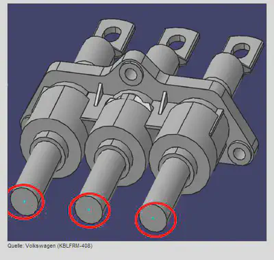
The picture above shows an example of connector with multiple segment connection points (sometimes also called bundle postion / connection points). The segment connection points are marked with red circles. Such connectors have multiple entry points for wires, that can be used alternatively or at the simultaniously. The geometric position of the segment connection points is different, that they have to be treated individually, so each segment connection point is accessed via an individual SegmentConnectionPoint
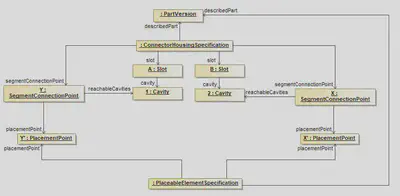
The example shows a connector that has two cavity, that are only reachable through different segment connection points. By associating these SegmentConnectionPoints with corresponding PlacementPoints the SegmentConnectionPoint become ‘placeable’ on nodes in the topology of a harness.
Wire Addons
Cavities
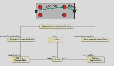
This example shows how add-ons for cavities in a connector could be defined. In this example, the ConnectorHousingSpecification has two different SegmentConnectionPoints. Each of them is defining it’s own CavityAddOn. So depending on the SegmentConnectionPoint used, a Cavity can have for example 50mm as well as 150mm as Add-On.
Modular Slots
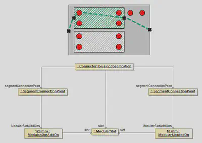
If a ConnectorHousingSpecification has ModularSlots, the Add-ons are not defined individually for all cavities for all possible inserts, but only per ModularSlot. The Add-On defined in the ModularSlotAddOn, is the Add-On need to reach the ModularSlot from the corresponding SegmentConnectionPoint. The add-on needed to reach a certain cavity in an used insert, can be obtain from ConnectorHousingSpecification of the used insert.
ConnectorHousingCap
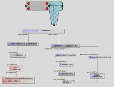
Wire add-ons caused by cap’s are defined in the ConnectorHousingCapSpecification. The specified value is the add-on required to reach the SegmentConnectionPoint of the ConnectorHousing from the entry point of the cap.
Splices
Before reading this implementation guideline, it is highly recommended to read the following sections in the VEC Online Model Description first:

A splice is normally used to create a contacting between multiple wires with the same potential e.g. for ground distribution. A splice can be created with or without real material (e.g. ultra-sonic welding vs. crimping). The figure above is a schematic illustration of the two common types of splices. On the left side is an end splice, on the right side an inline or parallel splice. The following sections will give you a comparison of those variants every time a different handling is needed. To do so the examples of an end splice with just two wire ends and an inline splice with one wire end on the left and two wire ends on the right will be used. (see figure 2 + 3)
Part Master Definition
Technical Properties
In the VEC the technical properties of splices are defined with a SpliceTerminalSpecification. The specification can represent a process definition (e.g. for ultra-sonic welding) or a real component (e.g. the sleeve for crimped splices).
The different types of splices are defined with the inner structure of the specification (WireReceptions and their relations)
 |  |
|---|---|
 WireReception is needed |  SpliceTerminalSpecification contains a wire reception for each side. |

InternalTerminalConnection, the default assumption is that all recepetions (wire & terminal) are short circuited (have the same potential). So, for most regular splices it is not required to defined InternalTerminalConnections.Placeability
To allow the placement of a splice in the topology it requires a PlaceableElementSpecification (compare Placement and Dimensions).
| In case of an inline splice it might be neccessary to know / to specify the orientation of the splice in the topology. The details of a placement are defined with individual PlacementPoints in the PlaceableElementSpecification.To associate this with the splice specific properties, a WireReception can reference the PlacementPoint that represents itself in the placement. |
Usage
Instantiation
Instances are required when using splices in a harness or wiring definition (see Instances of Components). Splice specific properties are defined with a SpliceTerminalRole. The role contains all instance information about the splice like sealing or insulation and it also contains a WireReceptionReference foreach WireReception in the part master definition.
| |
|---|---|
The end splice needs just one WireReceptionReference | In case of the inline splice two WireReceptionReferences have to be put in the SpliceTerminalRole |
To define reference elements for definition of the placement of a splice in the topolgy, a PlaceableElementRole has to be put inside the instance representation. This is valid for both example cases.
| When the direction of the inline splice shall be specified, it is necessary to create PlacementPointReferences underneath the PlaceableElementRole. They represent the spots of the splice which shall be placed in the topology instead of the whole splice itself. For the inline splice example two PlacementPointReferences are required, referencing the PlacementPoints from the master data definition. |
Contacting
Splices exist in 100% or 150% configurations (e.g. to create a ground distribution point for wires from different modules). The part master definition of the splice contains exactly one WireReception if it is an End-Splice. In case of an Inline (e.g. a Parallel Splice) the part master data definition contains as many Wirereceptions as directions exists from which a contacting can be realized.
Different predefined contacting variants (100%) of the splice are expressed by one ContactPoint per variant. If the splice has no variants, it defines just one ContactPoint. If the splice is undefined at design time and actual variants are only known at manufacturing time, one ContactPoint per WireEnd shall be used.
If different configurations require different terminal / contacting material (e.g. crimp sleeves) the corresponding material needs to be expressed by a new splice instance (part master data + instance + contact points for all variants with new material). This is the same situation when a certain position can be realized with connector housing with different number of cavities. If different configurations require (different) additional material (e.g. sealings) it is also referenced from the ContactPoints as WireEndAccessory.
For inline splices (more than one WireReception) there are situations where the allocation of wires to sides / wire receptions is free or is not explicitly defined. However, if it necessary to defines this assignment explicitly WireMountingDetails are added to the WireMounting in the ContactPoint. The WireMountingDetail defines which WireEnds are related to which WireReceptionReference.
Placement
The splice terminal is placed in the topology with a Placement contained in a PlacementSpecification and a PlaceableElementRole contained in the OccurrenceOrUsage. A detailed description can be found in the specification “Placement and Dimensions” and corresponding implementation guideline.
If a splice has more than one WireReception and if it is required to define the exact orientation of the splice in the topology, or the splice has such a size that the exact positioning makes a geometrical difference (e.g. high voltage splices), then such a definition is possible in the VEC.
A prerequisite for this is, that the topology has to define individual TopologyNodes for each WireReceptionReference, instead of one node, when orientation is irrelevant (see figure below).

The details of the placement are then defined with references between the corresponding NodeLocations and the PlacementPointReferences representing the WireReceptionReferences (compare the instance diagram below).
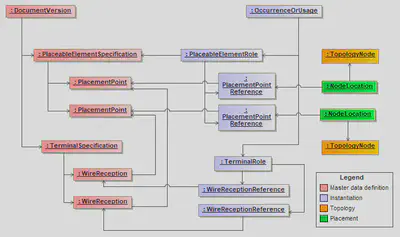
WireReceptionReferences, PlacementPointReferences etc. can be omitted.XML-Example
The following XML listings show an example of splice instance with placed WireReceptions
Part Master Data
<DocumentVersion id="documentVersion_1">
        [...]
        <ReferencedPart>partVersion_1</ReferencedPart>
        <Specification id="wireReceptionSpecification_1" xsi:type="vec:WireReceptionSpecification" >
            <Identification>SpliceReception</Identification>
            <CoreCrossSectionArea id="valueRange_1">
                <Minimum>0.5</Minimum>
                <Maximum>1.5</Maximum>
                [...]
            </CoreCrossSectionArea>
        [...]
        </Specification>
        <Specification id="spliceTerminalSpecification_1" xsi:type="vec:SpliceTerminalSpecification">
            <Identification>Splice</Identification>
            <DescribedPart>partVersion_1</DescribedPart>
            <WireReception id="wireReception_1">
                <Identification>Left</Identification>
                <WireReceptionSpecification>wireReceptionSpecification_1</WireReceptionSpecification>
                <PlacementPoint>placementPoint_1</PlacementPoint>
            </WireReception>
            <WireReception id="wireReception_2">
                <Identification>Right</Identification>
                <WireReceptionSpecification>wireReceptionSpecification_1</WireReceptionSpecification>
                <PlacementPoint>placementPoint_2</PlacementPoint>
            </WireReception>
        </Specification>
        <Specification id="placeableElementSpecification_1" xsi:type="vec:PlaceableElementSpecification">
            <Identification>Pes</Identification>
            <PlacementPoint id="placementPoint_1">
                <Identification>First</Identification>
            </PlacementPoint>
            <PlacementPoint id="placementPoint_2">
                <Identification>Second</Identification>
            </PlacementPoint>
        </Specification>
        [...]
    </DocumentVersion>

     <PartVersion id="partVersion_1">
        <CompanyName>The VEC Company Ltd.</CompanyName>
        <PartNumber>007_123</PartNumber>
        <PartVersion>1</PartVersion>
        <PrimaryPartType>SpliceTerminal</PrimaryPartType>
    </PartVersion>
Instance
<PartOccurrence id="partOccurrence_1">
        <Role xsi:type="vec:PlaceableElementRole" id="placeableElementRole_1">
             <Identification>PlaceableElementRole</Identification>
             <PlaceableElementSpecification>placeableElementSpecification_1</PlaceableElementSpecification>
             <PlacementPointReference id="placementPointReference_1">
                 <Identification>placementPointReference_1</Identification>
                 <PlacementPoint>placementPoint_1</PlacementPoint>
             </PlacementPointReference>
             <PlacementPointReference id="placementPointReference_2">
                 <Identification>placementPointReference_2</Identification>
                 <PlacementPoint>placementPoint_2</PlacementPoint>
             </PlacementPointReference>
         </Role>
        <Role xsi:type="vec:SpliceTerminalRole" id="spliceTerminalRole_1">
            <Identification>SpliceTerminalRole</Identification>
            <TerminalSpecification>spliceTerminalSpecification_1</TerminalSpecification>
            <WireReceptionReference id="wireReceptionReference_1">
                <Identification>Left</Identification>
                <WireReception>wireReception_1</WireReception>
            </WireReceptionReference>
            <WireReceptionReference id="wireReceptionReference_2">
                <Identification>Right</Identification>
                <WireReception>wireReception_2</WireReception>
            </WireReceptionReference>
        </Role>
        <Part>partVersion_1</Part>
    </PartOccurrence>
Placement
  <Specification xsi:type="vec:PlacementSpecification" id="placementSpecification_1">
        <Identification>PLACEMENT</Identification>
        <Placement xsi:type="vec:OnPointPlacement" id="placement_1">
            <Identification>Splice</Identification>
            <Location xsi:type="vec:NodeLocation" id="location_1">
                <Identification>Left</Identification>
                <ReferencedNode>node_1</ReferencedNode>
                <PlacedPlacementPoints>placementPointReference_1</PlacedPlacementPoints>
            </Location>
            <Location xsi:type="vec:NodeLocation" id="location_2">
                <Identification>Rigth</Identification>
                <ReferencedNode>node_2</ReferencedNode>
                <PlacedPlacementPoints>placementPointReference_2</PlacedPlacementPoints>
            </Location>
        </Placement>
        [...]
    </Specification>
    <Specification xsi:type="vec:TopologySpecification" id="topologySpecification_1">
        <TopologyNode id="node_1">
            <Identification>PNID1</Identification>
        </TopologyNode>
        <TopologyNode id="node_2">
            <Identification>PNID2</Identification>
        </TopologyNode>
    </Specification>
Accessories
Part Master Definition
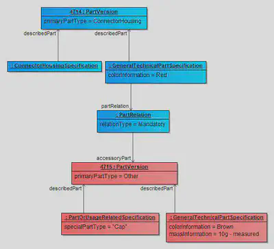
Part A being an accessory for Part B means, that if Part B is used somewhere in a harness, then Part A might (or must) be used as well. These can be for example backshells, connector housing locks, clips, cable ties. In the VEC, any part classification can be an accessory to another part. A relation between PartVersion and its accessories can be established with a PartRelation in a GeneralTechnicalPartSpecification
Example
The following table shows examples for the usage of a PartRelation and the corresponding semantic meanings.
| # | Example | Meaning | In numbers | ||
|---|---|---|---|---|---|
| 1 |
| The part A has to be used exactly 3 times or exactly 6 times. | 3 x A ; 6 x A | ||
| 2 |
| The part B has to be used exactly 0 times or exactly 2 times. | 0 x B ; 2 x B | ||
| 3 |
| The part C has to be used exactly 3 times. | 3 x C | ||
| 4 |
| The part C has to be used exactly 3 times. This is semantically equivalent with example #3. | 3 x C | ||
| 5 |
| The parts D & E & F have to be used exactly 1 times or 0 times. | 0..1 x (D,E,F) | ||
| 6 |
| The part G have to be used exactly 0 times or 2, 3, 5 times. | (0,2,3,5) x G | ||
| 7 |
| The part K have to be used between 3 and 6 times. | 3..6 x K |
Instantiation
As described in the previous section, definitions can be made the part master data which accessories are required in which combination for a component. In the implementation in the wiring harness, however, there are also degrees of freedom as to which accessories are actually used. Therefore, the master data can only define valid possibilities; which variant is used must be defined at the concrete occurrence.
In the VEC the accessory occurrence → parent occurrence relationship is represented by the ReferenceElement association, where the accessory occurrence references the OccurrenceOrUsage it depends on / relates to as ReferenceElement(see Instantiation of Components)
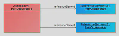
The illustration above shows a single accessory that is associated with two reference elements. In cases where the variance control mechanisms are not yet defined1 completely, the condition of existence of the reference elements has implications for the accessory.

An example for such case are elaborately sealed grommets for improved waterproofing. Each wire passing through the grommet requires a special individual seal. In this case, each seal is an accessory for both the wire and the grommet to the same extent. In concrete variants of the harness, only if a specific wire exists the corresponding seal is required. However, the association to the grommet is equally relevant, as it defines the position of the seal on the wire and without the grommet the seal is also without purpose.
For example not all elements have a specific
VariantConfigurationor not allOccurrenceOrUsageare controlled by modules or harness configurations. ↩︎
Grommets
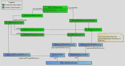
Grommets have certain points (the CableLeadThrough) that are relevant for the placement of a grommet. There are different types of grommets e.g. grommets with a y-shape (1 in, 2 outgoings) or larger ones and that reach through more than one metal plane like the ones for the door hinge (illustration below).

Up to VEC Version 1.1.3 the CableLeadThrough of a grommet was the significant point for the definition of a placement. However, this turned out to insufficient for a detailed definition, as the spatial extent of a grommet is often non-negligible. Therefore, since VEC 2.0.0 the significant point for a placement is the CableLeadThroughOutlets instead. Those can be associated with PlacementPoint and this is the point where the general concept of placements in the VEC attaches.
Channels
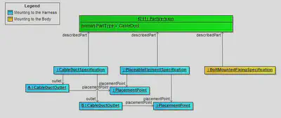
CableDucts can fulfill have to relevant aspects. They can be connected with the harness (placement). This is specified with the blue classes. The CableDuctSpecification brings this aspect of use to given part. At the same time a CableDuct can have properties of a Fixing since it is often mounted to the vehicle body as well. This aspect is defined by an additional FixingSpecification.
Fixings
With PlacementPoints
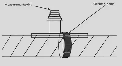
This illustration shows the Fixing with a PlacementPoint and MeasurementPoint as a PartOccurrence.
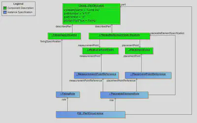
The ability to place a Fixing on a specific point in the topology is similar to Grommets covered by generic mechanism of PlacementPoint and PlacementPointReference. Additionally the measurement of Fixing is covered by MeasurementPoint and MeasurementPointReference.
Fixings with additional Cable Ties
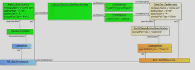
The diagram illustrates the definition of a Fixing with CableTies as Accessory. The upper half of the diagram is the definition of the part master data.
The Fixing is described with a PartVersion and a FixingSpecification. To describe its accessories it has GeneralTechnicalPartSpecification with PartRelations to link the accessories. In this case, one CableTie is mandatory, a second one is an optional add on. Both are referencing the PartVersion of the CableTie.
The CableTie is currently defined with a not further detailed PartOrUsageRelatedSpecification, since there is no CableTieSpecification in the VEC at the moment. That the accessory is a CableTie is defined by the value of the specialPartType attribute.
If there are any additional properties necessary for the CableTie, then they could be specified with CustomProperties (see CustomProperty) for the PartOrUsageRelatedSpecification.
For the instancing of these components, both are created with a PartOccurrence. The Fixing is defined with a FixingRole, the CableTie with a SpecificRole (For the same reasons why a PartOrUsageRelatedSpecification has been used).
Tapes and Tubes
Disclaimer: This page or section is currently under review by the community.
The content of this page or section can be subject to change at any time. If you find any issues or if you have any review comments please drop us an issue in our Issue Management on GitHub.
This page or section resolves #956
Wire protections in general are handled different than components with a fixed form like connectors, cable ducts or fixings. Tapes and Tubes are flexible components that can be adapted to the geometry of the wires they are protecting.
Placement
Unlike other components they are (mostly) not placed at specific points in the topology but rather along TopologySegments on whole areas of the topology.
How this type of placement works is described in detail in the section Placements and Dimensions. For tapings, however, there are also special application forms that do not extend over a continuous topological region but are applied only locally at specific points, for example spot tapes or cross-tapings.
Tapes
Tapes play a special role in the product definition. Unlike other components, such as connectors, they are not fully defined by their part specification (part number) alone, since this typically represents only the “tape on the roll”. For the product definition, however, the applied processing method is decisive. In the VEC, this is specified in the usage via the TapeRole.
This modeling approach is also used for other component types (e.g. for defining wire lengths), but the degrees of freedom are significantly greater for tapes. For example, the WindingType can directly influence the type of placement in the topology. A spiral wrapping is applied to a linear region of the topology, whereas spot tapes or cross-wrappings refer to a specific point location.
Groupings of Wire Protections
For various reasons, it may be necessary to represent more complex “protection constructs” in the product definition by multiple individual OccurrenceOrUsages, while in the actually manufactured product they should be realized as continuously as possible. Such a decomposition into several occurrences may be required because the nature of a variant-rich 150% product definition does not always allow a single, unambiguous definition (e.g. in one variant a subdivision is technically necessary, whereas in another it is not). Alternatively, different processing types may be applied with the same material in different regions, for example a change from spiral wrapping to dense wrapping, which likewise requires separate occurrences, as described in the previous section.
At the same time, it is desirable in the physical product to form protection regions that are as continuous as possible and to avoid interruptions in the protected area that are not technically required but are merely a consequence of the modeling approach in the product definition. The explicit definition of such areas is achieved with the WireProtectionGroup. Please revisit the definition of this class, before continuing.
The following figure illustrates such a situation, where a WireProtectionGroup can be applied:

The figure shows two E/E components A and B that are connected by a Y-shaped topology consisting of the topology segments SEG-1, SEG-2, and SEG-3. TopologySegments only exist in the physical product if wires actually run through them, and only in this case are corresponding protection elements required. In the present example, the two topology segments SEG-2 and SEG-3 exist only if the respective connected components A or B are present. SEG-1 exists as soon as at least one of the two components is present.
As illustrated, the entire region is intended to be protected by tape. In the example, this is defined by several PartOccurrences, labeled #1, #2, …, #7. If only one of the two components, for example A, exists, an optimal execution of the protection would be as follows:
- start wrapping at
#5, - continue seamlessly through
#2and#1, - finish the protected region at
#7, without interrupting the wrapping process at any point.
If both components exist, an optimal execution could be:
- start wrapping at
#6and wrap#3without interruption, - cut the tape, start again at
#5, wrap through#2and#1, finish at#7, - finally apply a cross-wrapping at
#4.
If the wrappings were executed strictly according to the individual occurrences defined in the product model, the wrapping would be interrupted at the junction of the two segments SEG-2 and SEG-3. In addition, separate start and end fixations would be required for each occurrence in order to achieve the required quality.
Alternatively, one could define the actually continuous wrapping regions as individual PartOccurrence (the VEC supports placements spanning multiple segments), for example by modeling the region #1–#2 as a single occurrence.
However, due to the variant-rich nature of the product, this would lead to high redundancy in the product definition and to variance control issues. For instance, the region at #1 would then have to be covered by at least two different occurrences: one for the case that A or A & B exist, and another one for the case that only B exists. It is easy to see that this approach becomes impractical for highly variant products.
This is where the WireProtectionGroup comes into play. It represents a requirement or work instruction stating, that the referenced protection elements should be executed as continuously as technically possible, while still allowing the individual elements to be controlled independently. In the example, all elements (#1–#7) would be grouped into a single WireProtectionGroup. The individual elements could then be controlled, for example, as described above for the different variant situations.
$$ A \Rightarrow \{ \#2, \#5 \} $$ $$ B \Rightarrow \{ \#3, \#6 \} $$ $$ (A \lor B) \Rightarrow \{ \#1, \#7 \} $$ $$ (A \land B) \Rightarrow \{ \#4 \} $$
The same logic is not limited to tapes but can also be applied, for example, to tubes. In this case, the semantics are analogous: if only A or only B exists, a continuous tube should be used for #1,#2 or #1, #3 respectively. If both exist, separate tube sections would be required for #1, #2, #3 and a Y-fitting would be used at position #4.
WireProtectionGroup are only meaningful if the group contains exclusively materials that allow for a continuous, uninterrupted transition.ECUs, EE-Components and Component Boxes
E/E components, represented in the VEC by the EEComponentSpecification and
EEComponentRole, summarize all kinds of components with a more or less
complex electrical function. In the VEC the description of an E/E component is a combination of
the following (optional) aspects:
- Connector Interface / EE Component Header: Defines the properties and possibilities for a connection to a wiring harness or other e/e components.
- Internal Connectivity: Defines the electrical connectivity within a e/e component.
- Switching States: Add variability of a certain degree to the internal connectivity.
- Electrical Interface: Defines the electrical properties (e.g. peak currents) of a connector interface (see Pinning).
- Type Specific Properties: Defines properties that apply only to specific e/e component types (e.g. capacity for a battery).
E/E Components in terms of the VEC can be for example:
Connector Interface / EE Component Header
Basic Structure
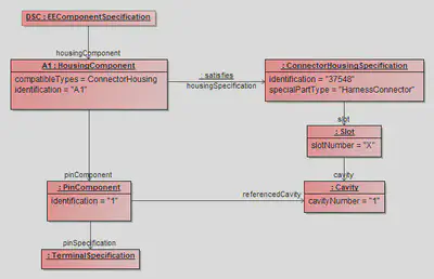
Any E/E-Component has some kind of connector interface. This can be an interface to attach a harness or another E/E component. For the variety of possible usage see the next section.
An E/E-Component is represented in the VEC by an EEComponentSpecification. The connector interface of an E/E-Component is represented by a HousingComponent. The HousingComponent separates into two aspect:
- Geometrical: It references a
ConnectorHousingSpecificationto describe the geometrical / mechanical properties of the connector, e.g. the shape, slot layout, number of cavities etc. As this is the sameSpecificationthat is used for harness connectors it just defines an empty housing, without pins and terminals. - Electrical: The electrical properties of the connector, the actual pins in the housing, are represented by the
PinComponent. The physical properties of the pin are represented by aTerminalSpecification.
The figure Instantiation Example shows the structure for an E/E component with a single pin. The following XML listing shows the same as xml snippet:
<Specification xsi:type=vec:EEComponentSpecification" id"id_ecomponent_spec_1498">
    <Identification>DSC</Identification>
    <DescribedPart>...</DescribedPart>
    <HousingComponent id="id_housing_comp_1500">
        <Identification>A1</Identification>
        <HousingSpecification>id_connect_hous_spec_1501</HousingSpecification>
        <PinComponent id="id_pin_comp_1506">
            <Identification>1</Identification>
            <PinSpecification>id_terminal_spec_1511</PinSpecification>
            <ReferencedCavity>id_cavity_1504</ReferencedCavity>
        </PinComponent>
    </HousingComponent>
</Specification>
<Specification xsi:type="vec:ConnectorHousingSpecification" id"id_connect_hous_spec_1501">
    <Identification>37548</Identification>
    <SpecialPartType>HarnessConnector</SpecialPartType>
    <Slot xsi:type="vec:Slot" id"id_slot_1502">
        <SlotNumber>A</SlotNumber>
        <Cavity id="id_cavity_1504">
            <CavityNumber>1</CavityNumber>
        </Cavity>
    </Slot>
</Specification>
<Specification xsi:type="vec:TerminalSpecification" id"id_terminal_spec_1511">
    <Identification>Usn3B323a4a10a614881C33</Identification>
    ...
</Specification>
Connector / Interface Types
Note: This section is in particular relevant for component boxes, as they have the greatest variance of different interface types. However, all these interface types can as well appear in other EE components. To understand the technical background and the definition of the different types, please read the article about Component Boxes
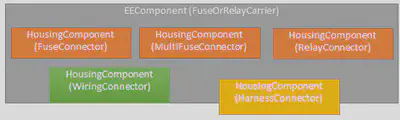
All (pluggable) electrical interfaces of a EE component to other components or the harness are
represented by a HousingComponent. That means for each fuse, multi fuse or relay
slot and for all pluggable harness connectors or direct contacting connectors a HousingComponent
is defined.
Each HousingComponent references a ConnectorHousingSpecification that defines the geometrical properties of the slot.
Version < 1.2.0: The classification of the housing component (e.g. is it a fuse or relay slot) is done with the
specialPartType of the associated ConnectorHousingSpecification.
Version >= 1.2.0: VEC 1.2.0 introduced a compatibleTypes attribute in the HousingComponent
to define what type of components are valid counter parts for a housing component. This is considered as an additional
information to the pre 1.2.0 way.
Note: Slots for multi fuses are also represented by one HousingComponent.
| Type of Slot | ConnectorHousingSpecification.SpecialPartType (V1.1.3) | HousingComponent.CompatibleTypes (V1.2.0) |
|---|---|---|
| Fuse slot | FuseConnector | Fuse |
| Multi fuse slot | MultiFuseConnector | MultiFuse |
| Relays slot | RelayConnector | Relay |
| Direct Contacting | WiringConnector | Terminal |
| Slot for Harness Connector | HarnessConnector | ConnectorHousing |
| Slot for Ring Terminals of a Harness | HarnessConnector | RingTerminal |
| Modular Slot for other E/E-Components | … | EEComponent |
In figure E/E-Component Interfaces the instantiation of such a structure is partially shown. The details of a
connector description with Slot, Cavity and PinComponent are
only implied on the left side.
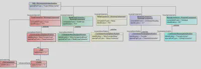
The listing below shows the general xml structure for such a component box. Omitted blocks are marked with “…”.
<Specification xsi:type="vec:EEComponentSpecification" id"id_ecomponent_spec_1463">
  <Identification>Dnq3202104816a236</Identification>
  <SpecialPartType>FuseOrRelayCarrier</SpecialPartType>
  <DescribedPart>id_part_ver_1419</DescribedPart>
  ...
  <HousingComponent id="id_housing_comp_1466">
      <Identification>B</Identification>
      <HousingSpecification>id_connect_hous_spec_1430</HousingSpecification>
      ...
  </HousingComponent>
  <HousingComponent id="id_housing_comp_1478">
      <Identification>G2</Identification>
      <HousingSpecification>id_connect_hous_spec_1459</HousingSpecification>
      ...
  </HousingComponent>
</Specification>

<Specification xsi:type="vec:ConnectorHousingSpecification" id"id_connect_hous_spec_1430">
  <Identification>WIRING</Identification>
  <SpecialPartType>WiringConnector</SpecialPartType>
  <Slot xsi:type="vec:Slot" id"id_slot_1432">
      ...
  </Slot>
</Specification>

<Specification xsi:type="vec:ConnectorHousingSpecification" id"id_connect_hous_spec_1459">
  <Identification>FUSE</Identification>
  <SpecialPartType>FuseConnector</SpecialPartType>
  <Slot xsi:type="vec:Slot" id"id_slot_1460">
      ...
  </Slot>
</Specification>
Internal Connectivity
Connections

This section applies to all kind of internal connections in E/E components. One of the major use cases for this is the representation of internal connectivity of component boxes, since this is an important information, for example for physical validation or the calculation of current flows in the network. The model elements can also be used to represent the internal connectivity of a relay or any other E/E component. However, when it comes to software enabled component states (e.g. ECUs) the feasibility is more than questionable.
In figure Component Box Schematic Illustration the internal connections are illustrated by the red and black lines (2).
In terms of the VEC, an InternalComponentConnection defines a logical (conductive) connection between
a number of PinComponent within a E/E component. This representation does not consider the actual realization
of the conductivity. This means, when multiple pins are connected, that the representation in the model is the same whether it is
realized by point to point connections, a conductor rail or direct contacting.
In figure Instancing for Internal Connections an instance diagram is shown for a power distribution connection between a supply on the left side and the individual fuse slots on the right side.
Note: The essential criteria for a InternalComponentConnection is the electrical conductivity. So even
if the connection in the example would be realized by three individual conductors between the left and the right side, it would be
represented by one InternalComponentConnection
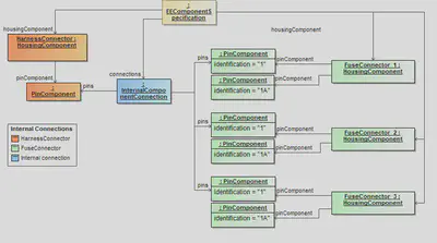
Switching States
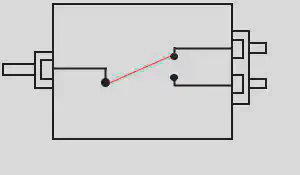
In figure Switching States Illustration a simple EEComponentSpecification with SwitchingState is schematically shown.
In figure Switching States the corresponding representation in VEC is shown. It is a simple switch with two states. In the example, the switch has two HousingComponent, meaning it has two connectors, one for the IN-side and one for OUT-side. The housing component for the IN-side has one PinComponent, the OUT-side has two of them. However, a real example could as well have just one HousingComponent with three PinComponent. The pin on the IN-side is connected to the pins on the OUT-side with a switchable XOR-connection.
The IN-side (highlighted in red) and the OUT-side (highlighted in green) are represented in the VEC as a connector interface of your choice, as described in Connector Interface / EE Component Header. In the VEC a InternalComponentConnection is free of variance, therefore each state of the XOR-connection of the example is represented by an individual InternalComponentConnection (A.1 -> B.1) and (A.1 -> B.2). The switch in this example has two switching states (B1 & B2), each referencing one InternalComponentConnection, meaning that if the state is active, the corresponding connections exist / have electrical conductivity. The fact, that B1 & B2 are mutally exclusive to each are other is currently not represented in the VEC.
Note: Without the additional information of the switching states, the representation with two InternalComponentConnection would be illegal, as it would semantically equivalent to representation with one InternalComponentConnection referencing three PinComponent
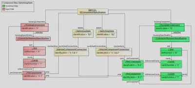
Internal Connectivity
With VEC version 2.2, a unified modeling approach for the internal connectivity of E/E-components has been introduced. This enhancement establishes a clear separation between the logical interconnection and the physical characteristics of internal connections and subcomponents.
To achieve this, proven VEC concepts from system schematic modeling and wiring representations are reused. At the same time, the new modeling approach offers two significant advantages:
- It enables a more flexible and open representation of complex aspects of internal connectivity, such as termination resistors or eFuses.
- It allows the consistent use of library components both in the system schematic and on the wiring level.
This approach builds on existing concepts like ConnectionSpecification, ComponentNode, and PartUsage to enable a structured and traceable definition of internal behavior within E/E-components.
Overview

The illustration above provides a high-level overview of the new internal connectivity concept and is divided into four quadrants. The right side represents master data or library information, while the left side shows the application in a specific context. The upper half of the diagram covers the logical layer, whereas the lower half represents the physical layer.
Logical Layer
The logical layer on both sides is modeled using the ConnectionSpecification.
On the master data side, the E/E component is represented by a single ComponentNode with associated childNodes and Connections.
On the usage side, this node can be cloned (with or without internal structure) and embedded into a larger system context. The link between the representation in the usage context and the original master data is established through a ReusageSpecification.
Physical Layer
On the physical layer, the master data side is described by an EEComponentSpecification, which - under the new modeling approach - only defines the outer envelope of the component.
The previously used InternalComponentConnection and FuseComponent is now deprecated.
Instead, traceability relationships between elements of the EEComponentSpecification (such as HousingComponent and PinComponent) and the logical connectivity model are introduced.
If internal elements of an E/E-component require a physical characterization (e.g., conductor cross-section or fuse trip current), the EEComponentSpecification includes a bill of materials modeled as subcomponents (e.g., PartUsage). These subcomponents define the physical properties and can be linked to the corresponding logical elements via “Realization” relationships (as known from the Wiring Specification).
On the usage side, the E/E-components are instantiated using an EEComponentRole contained in a PartOccurrence or PartUsage with the corresponding “Instantiation” relationships between usage and part master data. The necessary “Realization” relationships are available to map to the corresponding elements in the logical layer (also aligned with the wiring approach).
Traceability
As shown in the conceptual illustration, full traceability is ensured within the model. This is achieved by enabling the relevant elements in each quadrant to reference:
- Horizontally: from the usage context (left) to the master data definition (right),
- Vertically: from the physical layer (bottom) to the logical layer (top).
These directional references are realized through appropriate VEC concepts and allow consistent navigation and validation across different modeling perspectives.
Concrete Example
The following section uses a concrete example to demonstrate the application of the four-quadrant model and the relationships between them. A schematic representation of the example is shown in the following illustration.

The example consists of a component with a single external interface A comprising pins 1–5, a fixed (non-removable) fuse F1, a fuse socket F2, and a built-in relay R1, as well as the corresponding internal connectivity.
Part Master Data

The illustration shows the basic structure of the master data description of an E/E component with internal connectivity, focusing on the specification level and their overall relationships.
The logical layer of the internal connectivity is represented by a ConnectionSpecification, while the physical layer is modeled using PartUsages within a PartUsageSpecification.
Elements on the physical side maintain traceability links to the corresponding elements in the ConnectionSpecification (indicated by dashed lines in the diagram).
Each PartUsage references a specific PartOrUsageRelatedSpecification (e.g., a FuseSpecification or WireSpecification) to define the technical characteristics of the respective internal element. To clearly indicate that these internal PartUsages are contained within the E/E component, they are referenced by a PartStructureSpecification describing the PartVersion of the E/E component.
The technical characteristics of the E/E component itself, especially its external interface, are defined by a EEComponentSpecification.
The elements of this specification (e.g., HousingComponent, PinComponent) also maintain traceability links (shown as dashed arrows in the diagram) that reference their corresponding elements in the ConnectionSpecification.
The XML representation of this top level structure for the example would look like this:
<vec:VecContent xmlns:xsi="http://www.w3.org/2001/XMLSchema-instance" xmlns:vec="http://www.prostep.org/ecad-if/2011/vec" id="Content_00000" xsi:schemaLocation="">
  ...
  <DocumentVersion id="DocumentVersion_00001">
    <CompanyName>Acme Inc.</CompanyName>
    <DocumentNumber>DRAW-EE-COMP</DocumentNumber>
    <DocumentType>PartMaster</DocumentType>
    <DocumentVersion>1</DocumentVersion>
    <ReferencedPart>PartVersion_00151</ReferencedPart>
    <!-- General Properties of the E/E component -->
    <Specification xsi:type="vec:GeneralTechnicalPartSpecification" id="GeneralTechnicalPartSpecification_00002">...</Specification>
    <!-- Internal Connectivity (Logical Layer) -->
    <Specification xsi:type="vec:ConnectionSpecification" id="ConnectionSpecification_00003">...</Specification>
    <!-- Technical properties of pins & connectors (A & F2) of the E/E component -->
    <Specification xsi:type="vec:PluggableTerminalSpecification" id="PluggableTerminalSpecification_00054">...</Specification>
    <Specification xsi:type="vec:ConnectorHousingSpecification" id="ConnectorHousingSpecification_00055">...</Specification>
    <Specification xsi:type="vec:ConnectorHousingSpecification" id="ConnectorHousingSpecification_00062">...</Specification>
    <!-- Technical properties of the E/E component itself -->
    <Specification xsi:type="vec:EEComponentSpecification" id="EEComponentSpecification_00066">...</Specification>
    <!-- Technical properties of the Fuse subcomponent component (F1) -->
    <Specification xsi:type="vec:FuseSpecification" id="FuseSpecification_00076">...</Specification>
	<!-- Technical properties of the Relay subcomponent component (R1) -->
    <Specification xsi:type="vec:RelaySpecification" id="RelaySpecification_00078">...</Specification>
	<!-- Technical properties of the internal conductors -->
    <Specification xsi:type="vec:CoreSpecification" id="CoreSpecification_00079">...</Specification>
    <Specification xsi:type="vec:WireElementSpecification" id="WireElementSpecification_00081">...</Specification>
    <Specification xsi:type="vec:WireSpecification" id="WireSpecification_00082">...</Specification>
	<!-- The internal bill of material of the E/E component -->
    <Specification xsi:type="vec:PartStructureSpecification" id="PartStructureSpecification_00084">...</Specification>
	<!-- Part usages for sub components of the E/E component (F1, R1, internal conductors) -->
    <Specification xsi:type="vec:PartUsageSpecification" id="PartUsageSpecification_00085">...</Specification>
  </DocumentVersion>
  ...
  <PartVersion id="PartVersion_00151">
    <CompanyName>Acme Inc.</CompanyName>
    <PartNumber>EE-COMP</PartNumber>
    <PartVersion>1</PartVersion>
    <PrimaryPartType>EEComponent</PrimaryPartType>
  </PartVersion>
Logical Layer
As previously mentioned, the logical layer is represented by a ConnectionSpecification.
For the sake of clarity, the following XML snippet includes only the elements required to describe the red supply connection from A.1 to F1.A.1 and F2.A.1. The complete logical structure can be found in the accompanying XML file.
  <Specification xsi:type="vec:ConnectionSpecification" id="ConnectionSpecification_00003">
      <Identification>SCHEMATIC</Identification>
      <ComponentNode id="ComponentNode_00004">
        <Identification>EE-COMP</Identification>
        <ChildNode id="ComponentNode_00005">
          <Identification>F1</Identification>
          <ComponentConnector id="ComponentConnector_00006">
            <Identification>A</Identification>
            <ComponentPort id="ComponentPort_00007">
              <Identification>1</Identification>
            </ComponentPort>
            ...
          </ComponentConnector>
        </ChildNode>
        <ChildNode id="ComponentNode_00009">
          <Identification>R1</Identification>
          <ComponentConnector id="ComponentConnector_00010">
            <Identification>A</Identification>
            ...
          </ComponentConnector>
        </ChildNode>
        <ComponentConnector id="ComponentConnector_00019">
          <Identification>A</Identification>
          <ComponentPort id="ComponentPort_00020">
            <Identification>1</Identification>
            <Description xsi:type="vec:LocalizedString" id="LocalizedString_00021">
              <LanguageCode>En</LanguageCode>
              <Value>Power</Value>
            </Description>
          </ComponentPort>
          ...
        </ComponentConnector>
        <ComponentConnector id="ComponentConnector_00030">
          <Identification>F2</Identification>
          <ComponentPort id="ComponentPort_00031">
            <Identification>1</Identification>
            <Description xsi:type="vec:LocalizedString" id="LocalizedString_00032">
              <LanguageCode>En</LanguageCode>
              <Value>F2 - Pluggable</Value>
            </Description>
          </ComponentPort>
          ...
        </ComponentConnector>
      </ComponentNode>
      <Connection id="Connection_00035">
        <Identification>POWER</Identification>
        <ConnectionEnd id="ConnectionEnd_00036">
          <Identification>EE-COMP.A.1</Identification>
          <IsExternalEnd>false</IsExternalEnd>
          <ConnectedComponentPort>ComponentPort_00020</ConnectedComponentPort>
        </ConnectionEnd>
        <ConnectionEnd id="ConnectionEnd_00037">
          <Identification>EE-COMP.F2.1</Identification>
          <IsExternalEnd>false</IsExternalEnd>
          <ConnectedComponentPort>ComponentPort_00031</ConnectedComponentPort>
        </ConnectionEnd>
        <ConnectionEnd id="ConnectionEnd_00038">
          <Identification>F1.A.1</Identification>
          <IsExternalEnd>true</IsExternalEnd>
          <ConnectedComponentPort>ComponentPort_00007</ConnectedComponentPort>
        </ConnectionEnd>
      </Connection>
      ...
    </Specification>
Physical Layer
The first building block of the physical layer is the EEComponentSpecification itself, which represent the outer interface of the E/E component.
The XML representation below is shortened down to the Pin 1 in the Connector A.
    <Specification xsi:type="vec:EEComponentSpecification" id="EEComponentSpecification_00066">
      <Identification>EECS-EE-COMP</Identification>
      <DescribedPart>PartVersion_00151</DescribedPart>
      <!-- Traceability link to the logical layer -->
      <ComponentNode>ComponentNode_00004</ComponentNode>
      <HousingComponent id="HousingComponent_00067">
        <Identification>A</Identification>
        <!-- Traceability link to the logical layer -->
        <ComponentConnector>ComponentConnector_00019</ComponentConnector>
        <HousingSpecification>ConnectorHousingSpecification_00055</HousingSpecification>
        <PinComponent id="PinComponent_00068">
          <Identification>1</Identification>
          <!-- Traceability link to the logical layer -->
          <ComponentPort>ComponentPort_00020</ComponentPort>
          <PinSpecification>PluggableTerminalSpecification_00054</PinSpecification>
          <ReferencedCavity>Cavity_00057</ReferencedCavity>
        </PinComponent>
        ...
      </HousingComponent>
      <HousingComponent id="HousingComponent_00073">
        <Identification>F2</Identification>
        ...
      </HousingComponent>
    </Specification>
The second building block of the physical layer are the technical properties of the internal components. The XML listing below shows the relevant elements for the fuse F1 and for a single internal connection.
    <!-- technical properties for the fuse -->
    <Specification xsi:type="vec:FuseSpecification" id="FuseSpecification_00076">
      <Identification>FS-F1</Identification>
      <DescribedPart></DescribedPart>
      <IMax id="NumericalValue_00077">
        <UnitComponent>SIUnit_00152</UnitComponent>
        <ValueComponent>15.0</ValueComponent>
      </IMax>
    </Specification>
	<!-- technical properties for the conductor -->
    <Specification xsi:type="vec:CoreSpecification" id="CoreSpecification_00079">
      <Identification>BUSBAR</Identification>
      <CrossSectionArea id="NumericalValue_00080">
        <UnitComponent>SIUnit_00153</UnitComponent>
        <ValueComponent>5.0</ValueComponent>
      </CrossSectionArea>
    </Specification>
    <Specification xsi:type="vec:WireElementSpecification" id="WireElementSpecification_00081">
      <Identification>BUSBAR</Identification>
      <ConductorSpecification>CoreSpecification_00079</ConductorSpecification>
    </Specification>
    <Specification xsi:type="vec:WireSpecification" id="WireSpecification_00082">
      <Identification>WS-BUSBAR</Identification>
      <DescribedPart></DescribedPart>
      <WireElementSpecification>WireElementSpecification_00081</WireElementSpecification>
      <WireElement id="WireElement_00083">
        <Identification>BUSBAR</Identification>
        <WireElementSpecification>WireElementSpecification_00081</WireElementSpecification>
      </WireElement>
    </Specification>
    ...
    <Specification xsi:type="vec:PartUsageSpecification" id="PartUsageSpecification_00085">
      <Identification>VIRTUAL COMPONENTS</Identification>
	  <!-- PartUsage for the internal conductor -->
      <PartUsage id="PartUsage_00086">
        <Identification>POWER</Identification>
        <Role xsi:type="vec:WireRole" id="WireRole_00087">
          <Identification>POWER</Identification>
          <WireSpecification>WireSpecification_00082</WireSpecification>
          <WireElementReference id="WireElementReference_00088">
            <Identification>BUSBAR</Identification>
			<!-- traceability link to the logical layer -->
            <Connection>Connection_00035</Connection>
            <ReferencedWireElement>WireElement_00083</ReferencedWireElement>
          </WireElementReference>
        </Role>
        <PrimaryPartUsageType>Wire</PrimaryPartUsageType>
        <PartOrUsageRelatedSpecification>WireSpecification_00082</PartOrUsageRelatedSpecification>
      </PartUsage>
      ...
	  <!-- PartUsage for the integrated fuse -->
      <PartUsage id="PartUsage_00104">
        <Identification>F1</Identification>
        <Role xsi:type="vec:FuseRole" id="FuseRole_00105">
          <Identification>F1</Identification>
          <EEComponentSpecification>FuseSpecification_00076</EEComponentSpecification>
		  <!-- traceability link to the logical layer -->
          <ComponentNode>ComponentNode_00005</ComponentNode>
        </Role>
        <PrimaryPartUsageType>Fuse</PrimaryPartUsageType>
        <PartOrUsageRelatedSpecification>FuseSpecification_00076</PartOrUsageRelatedSpecification>
      </PartUsage>
    </Specification>
Last but not least, the PartUsages are assigned to the E/E-component as subcomponents with a PartStructureSpecification.
    <Specification xsi:type="vec:PartStructureSpecification" id="PartStructureSpecification_00084">
      <Identification>STRUCTURE</Identification>
      <DescribedPart>PartVersion_00151</DescribedPart>
      <InBillOfMaterial>PartUsage_00086 PartUsage_00089 PartUsage_00092 PartUsage_00095 PartUsage_00098 PartUsage_00101 PartUsage_00104 PartUsage_00106</InBillOfMaterial>
    </Specification>
Usage
The master data definitions described in the previous sections can be used on both the logical and the physical layer. However, the instantiation concepts differ between the two layers.
Logical Layer
On the logical layer, this constitutes a reuse of information. The same concepts (i.e., classes and attributes) are used in both the master data and the usage context. That means a ConnectionSpecification is used on both sides to describe the logical connectivity. However, the usage of a ComponentNode may deviate from its master definition, according to process-specific rules. For example, the identification (name) of a ComponentNode in the master data may differ from its designation in a specific usage context.
To enable traceability between usage and master data, a ReusageSpecification is used.
The corresponding XML representation is shown below.
The ConnectionSpecification from the master data was already listed earlier.
  <DocumentVersion id="DocumentVersion_00108">
    <CompanyName>Acme Inc.</CompanyName>
    <DocumentNumber>SCHEMATIC</DocumentNumber>
    <DocumentVersion>1</DocumentVersion>
    <Specification xsi:type="vec:ConnectionSpecification" id="ConnectionSpecification_00109">
      <Identification>SCHEMATIC</Identification>
	  <!-- Reuse of EE-COMP, renamed to A200 -->
      <ComponentNode id="ComponentNode_00110">
        <Identification>A200</Identification>
        <ComponentConnector id="ComponentConnector_00111">
          <Identification>A</Identification>
          <ComponentPort id="ComponentPort_00112">
            <Identification>1</Identification>
          </ComponentPort>
          ...
        </ComponentConnector>
        <ComponentConnector id="ComponentConnector_00117">
          <Identification>F2</Identification>
          ...
        </ComponentConnector>
      </ComponentNode>
    </Specification>
    <Specification xsi:type="vec:ReusageSpecification" id="ReusageSpecification_00120">
      <Identification>RS-DRAW-EE-COMP-SCHEMATIC</Identification>
      <Reusage id="Reusage_00121">
	  	<!-- Traceability link into part master data -->
        <Template>ComponentNode_00004</Template>
        <Usage>ComponentNode_00110</Usage>
      </Reusage>
      <Reusage id="Reusage_00122">
	  	<!-- Traceability link into part master data -->
        <Template>ComponentConnector_00019</Template>
        <Usage>ComponentConnector_00111</Usage>
      </Reusage>
      <Reusage id="Reusage_00123">
	  	<!-- Traceability link into part master data -->
        <Template>ComponentPort_00020</Template>
        <Usage>ComponentPort_00112</Usage>
      </Reusage>
	  ...
    </Specification>
  </DocumentVersion>
Physical Layer
In the physical layer the VEC has an actual instantiation approach with different concepts for types (e.g. PartVersion, PartOrUsageRelatedSpecification) and instances (PartOccurrence, Role). However, these concepts have also the capability to provide traceability into the logical layer, as shown the listing below:
  <DocumentVersion id="DocumentVersion_00131">
    <CompanyName>Acme Inc.</CompanyName>
    <DocumentNumber>HARNESS-1</DocumentNumber>
    <DocumentType>HarnessDescription</DocumentType>
    <DocumentVersion>1</DocumentVersion>
    <Specification xsi:type="vec:CompositionSpecification" id="CompositionSpecification_00132">
      <Identification>COMPONENTS</Identification>
      <Component id="PartOccurrence_00133">
        <Identification>A200*1</Identification>
        <Role xsi:type="vec:EEComponentRole" id="EEComponentRole_00134">
          <Identification>A200*1</Identification>
          <EEComponentSpecification>EEComponentSpecification_00066</EEComponentSpecification>
		  <!-- Traceability link into logical layer -->
          <ComponentNode>ComponentNode_00110</ComponentNode>
          <!--Embedded ConnectorHousingRole omitted.-->
          <HousingComponentRef id="HousingComponentReference_00135">
            <Identification>A</Identification>
			<!-- Traceability link into logical layer -->
            <ComponentConnector>ComponentConnector_00111</ComponentConnector>
            <HousingComponent>HousingComponent_00067</HousingComponent>
            <PinComponentRef id="PinComponentReference_00136">
              <Identification>1</Identification>
              <PinComponent>PinComponent_00068</PinComponent>
              <TerminalRole xsi:type="vec:BoltTerminalRole" id="BoltTerminalRole_00137">
                <Identification>1</Identification>
				<!-- Traceability link into logical layer -->
                <ComponentPort>ComponentPort_00112</ComponentPort>
                <TerminalSpecification>PluggableTerminalSpecification_00054</TerminalSpecification>
              </TerminalRole>
            </PinComponentRef>
            ...
          </HousingComponentRef>
          ...
        </Role>
        <Part>PartVersion_00151</Part>
      </Component>
    </Specification>
  </DocumentVersion>
Fuses
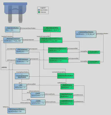
A single fuse is a two-terminal component that can be plugged or screwed into a compatible fuse slot. There are different types, which differ in their geometry, the type of connection, the tripping characteristics and their rated voltage.
In VEC a fuse is handled as a EE-Component and that is why the FuseSpecification extends the EEComponentSpecification and describes it’s the available connector interface also with a HousingComponent and - in this case - with two PinComponents. The FuseSpecification defines the typical component attributes, i.e. the maximum electric current information for the fuse.
In addition to that the geometrical structure is described by a ConnectorHousingSpecification with it’s Slots and their Cavities (Cavity ). The PinComponents can be described in a more detailed way by usage of the PinComponentBehavior. Special information about the signal, signal direction or voltage can be placed here.
The PinComponent can reference a TerminalSpecification to define the physical properties of the pin. To avoid the confusion by too many crossing lines, the connection t the TermnalSpecification is not explicitly drawn in the diagram above.
Instantiating fuses
Instantiating fuses is like instantiating any other EE-Component. A EEComponentRole under a PartOccurrence references the FuseSpecification and all structure elements underneath will be instantiated and references their corresponding part master element, too. For more information see E/E-Components.
Multi Fuses
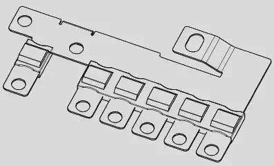
A mutlifuse is a special type of fuse that combines multiple fuses in a single component (see Multi Fuse Illustration). In contrast to a regular fuse, where there are only two interchangeable pins, the multi fuse has a single dedicated supplying pin and multiple protected pins.
An individual fuse component is located between each protected pin and the supplying pin. Each fuse component can have its own technical properties (e.g. max current).
As shown in figure Specification Multi Fuse a multi fuse is represented in the VEC by a MultiFuseSpecification, which is a specialization of the EEComponentSpecification. Therefore all aspects described in the general section potentially apply to multi fuses as well. This sample describes only the aspects that are specific for multi fuses.
In the VEC, a multi fuse has one HousingComponent with a PinComponent for each pin. Each integrated fuse in the multifuse is represented by a FuseComponent. The fuse component references the pin components that are connected through it and specifies the properties for this (e.g. iMax) through a FuseSpecification.
The geometrical shape of the multi fuse is defined by a ConnectorHousingSpecification with Slot and Cavity. The cavities are referenced by the pin components.
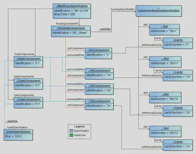
<Specification id="id_2000_0" xsi:type"vec:MultiFuseSpecification">
	<Identification>MF-3x100</Identification>
	<DescribedPart>id_1001_0</DescribedPart>
	<HousingComponent id="id_2023_0">
		<Identification>Hco-MF-3x100</Identification>
		<HousingSpecification>id_2000_1</HousingSpecification>
		<PinComponent id="id_2024_0">
			<Identification>V</Identification>
			<Description id="id_1003_1" xsi:type"vec:LocalizedString">
				<LanguageCode>De</LanguageCode>
				<Value>Versorgung</Value>
			</Description>
			<ReferencedCavity>id_2020_3</ReferencedCavity>
		</PinComponent>
		<PinComponent id="id_2024_1">
			<Identification>1A</Identification>
			<ReferencedCavity>id_2020_0</ReferencedCavity>
		</PinComponent>
		<PinComponent id="id_2024_2">
			<Identification>2A</Identification>
			<ReferencedCavity>id_2020_1</ReferencedCavity>
		</PinComponent>
		<PinComponent id="id_2024_3">
			<Identification>3A</Identification>
			<ReferencedCavity>id_2020_2</ReferencedCavity>
		</PinComponent>
	</HousingComponent>
	<IMaxTotal id="id_2080_0">
		<UnitComponent>id_1005_0</UnitComponent>
		<ValueComponent>300.0</ValueComponent>
	</IMaxTotal>
	<FuseComponents id="id_2046_0">
		<Identification>F1</Identification>
		<ConnectedPins>id_2024_0 id_2024_1</ConnectedPins>
		<FuseSpecification>id_2000_3</FuseSpecification>
	</FuseComponents>
	<FuseComponents id="id_2046_1">
		<Identification>F2</Identification>
		<ConnectedPins>id_2024_0 id_2024_2</ConnectedPins>
		<FuseSpecification>id_2000_3</FuseSpecification>
	</FuseComponents>
	<FuseComponents id="id_2046_2">
		<Identification>F3</Identification>
		<ConnectedPins>id_2024_0 id_2024_3</ConnectedPins>
		<FuseSpecification>id_2000_3</FuseSpecification>
	</FuseComponents>
</Specification>
Relays
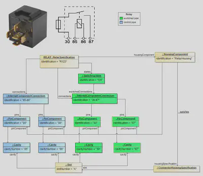
A relay is a component for switching current loads. Unlike fuses, there are more than one input pin and one output pin (number of pins >3). Some components, referred to as relays, are in reality small controllers with up to 17 pins.
In the VEC schema a relay is a special type of an EE-Component. It also owns a HousingComponent with it’s PinComponents underneath where these HousingComponent can be defined more detailed with a ConnectorHousingSpecification and the PinComponents with a referenced TerminalSpecification. Also the InternalComponentConnection for (potentially) connected pins are defined.
Additionally to these standard EE-Component structure the RelaySpecification also can contain so called SwitchingStates. Each state describes an InternalComponentConnection as potentially existing, depending on the current switched state of the relay. In the example above the blue colored PinComponents describe the coi contact. The connection between the two pins 30 and 87 is permanently The green colored part describes the switch, whose connection can exist depending on the SwitchingState. So the InternalComponentConnection between the pins 85 and 86 is not permanently guaranteed.
For more information see Switching States.
Instantiating relays
Instantiating relays is like instantiating any other EE-Component. A EEComponentRole under a PartOccurrence references the RelaySpecification and all structure elements underneath will be instantiated and references their corresponding part master element, too. For more information see chapter E/E-Components.
Component Boxes
Note: The following sections will cover the technical background about component boxes. The term “component box” will be used as a general term for all types of fuse and/or relay carrier, power distribution box etc. The detailed mapping of the different aspects on concepts of the VEC will be in EE-Components, as the concepts are the same for regular E/E components and component boxes.
Overview
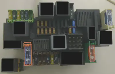
The image on the right side shows a photo of the front side of a component box. The drawing shows a drawing of a component box. In general, a component box is a component (carrier) that can be equipped with other components (e.g. relays & fuses) and by this, provides fusing and switching functionality to the attached wiring harness.
Basically a component box can be divided into four aspects:
- Slots to plug-in E/E components like fuses and relays.
- Connectivity with the wiring harness.
- Internal connectivity.
- Modularity
For all of these aspects, different technical solutions and variants exist. In reality, a specific component box can virtually combine and mix up all of these solution variants. To create a concise representation of a component box in the VEC model, a combination of different concepts is necessary. Some of these concepts are not exclusively for component boxes.

Plugability of E/E components
As mentioned before, a component box provides slots to plug-in other E/E-components. The following sections give brief overview of the most relevant types.
Fuse
A fuse is a component with two pins that can be plugged or screwed into a compatible fuse slot. There exists a wide range of different types that have individual triggering characteristics and currents, geometries, connection types etc.
Multifuse
A multi fuse is similar to a regular fuse. However, due to cost and packaging reasons multiple fuses are combined into a single component. The individual fuses share the power supply, see the multi fuse example.
Relais
A Relais is a component used for switching of loads and has more than 3 pins.
Direct and Indirect Contacting
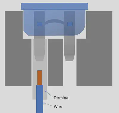
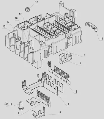
There are two different ways to create an electrical connection between the end of a wire and a corresponding fuse or relays, direct and indirect contacting. In case of direct contacting (see direct contacting) a terminal directly attached to the wire is locked into a cavity on ones side of the component box. The cavity goes through the component box and the pins of the fuse are directly plugged into the reception of the wire terminal. In this case, the component box itself does not provide a electrical conductivity.
In case of indirect contacting the component box contains a conductor (e.g. a conductor rail) that connects multiple cavities of the component box, see #3, #4, #7 and #9 in the component box drawing. The pins of the fuse are plugged into receptions of the conductor rail. Same applies for the connection to the harness. The wire terminals are grouped together into a harness connector, which is then attached to the component box. The conductor rail is often used for implementing the power distribution on the input side of a component box. In this case, the connection to the wiring harness is often done with ring terminals attached to bolts of the component box, see #8, #13, #14 and #16 in the component box drawing.
A combination of both in one component box is possible (and likely), e.g. the supplying side is realized with a conductor rail (indirect contacting) and the protected side is realized with direct contacting.
Connectivity with the Wiring Harness
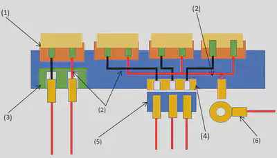
In case of direct contacting the component box itself serves as end point for the wires. Therefore the last topology segment is attached to the component box. The component box requires / provides segment connection points. From an abstract point of view and out of the perspective of the wiring harness, a component box with direct contacting behaves just like a regular harness connector, see the schematic illustration (3).
In case of indirect contacting the wires and terminals are clipped into a regular harness connector and the connector is plugged into the component box. So, again from an abstract point of view and out of the perspective of the wiring harness, the component box with indirect contacting and a harness connector behaves just like a regular E/E-Component (e.g. an ECU, an actor or a sensor), see the schematic illustration (4) & (5).
Another variant in case of indirect contacting is the usage of ring terminals. The component box provides a bolt and a wire is attached to it with a ring terminal. In this case the component box behaves like a battery or a ground bolt, see the schematic illustration (6) .
Internal Connectivity
For the calculation of current paths or electrical testing, a component box needs to define an internal connectivity, see the schematic illustration (2). This is a logical connectivity and it is irrelevant, if it is realized with direct or indirect contacting.
Modularity
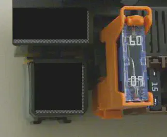
Some component boxes support modular concepts, e.g. the one shown in the photo. That means the component box can be extended with additional carriers, sockets or smaller component boxes (in a LEGO like way). There are two concepts for modularity: with or without electrical connectivity. If you compare the photo on top with the photo on the right you can see, that the relays socket in the lower left corner is mechanically clipped to main component box, electrically it is independent.
In contrast to this, the orange fuse socket right beside the relay socket has its upper part plugged into the main component box, with electric connectivity for power supply. The lower part of it provides an independent cavity for direct contacting of the protected side.
Pinning
The following section contains examples for the definition of Pinning information in the VEC. This means the specification of the electrical behavior of PinComponents. Make sure you have read the chapter “Pinning Information & Pinning Variance” before.
PinComponentBehaviors
To define the electrical behavior of a PinComponent the PinComponentBehavior is used. It is possible, that a PinComponent has more has multiple behaviors, which are configuration dependent (e.g. software defined pins on an ECU). Therefore, the PinComponentBehavior is a ConfigurableElement. With a PinComponentBehavior various electrical characteristics of the pin can be described. The next sections contain examples for that.
PinComponentType and SignalDirection
The figure below illustrates three E/E-components in a power distribution scenario and the logical correlations between them. Please note that the illustration is an excerpt from the master data. Actual relationships would only be established during the use / instantiation e.g. in a wiring. This is taken into account in that the logical relationships are only indicated by dependencies (dashed arrows).
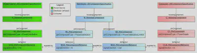
Our SPDS (Simple Power Distribution System :winking_face:) consists of the three components, a PowerSource (e.g. a Battery), a Distributor and a Consumer.
The PowerSource on the left side has a PinComponent with pinComponentType='PowerDistribution' and signalDirection='Out', because it distributes power to other components.
The Consumer on the right side has a PinComponent with pinComponentType='PowerSupply' and signalDirection='In', because the component itself is supplied with power over that pin.
The Distributor is software-defined eFuse in the example, it has two PinComponents. One “B1” is used to receive power, for distribution to others, therefore it is defined with pinComponentType='PowerDistribution' and signalDirection='In'. This should not be confused with pinComponentType='PowerSupply', which indicates that the received power is used to supply the component itself with energy. The second pin “B2” is defined with pinComponentType='PowerDistributionLimited' and signalDirection='Out'. This is because the pin is limited by an eFuse. For a conventional limitation (e.g. melting fuse) the fusing would be available via the internal connectivity of the E/E component and the pinComponentType='PowerDistribution' would be used.
Signal Peak Distance and Duration
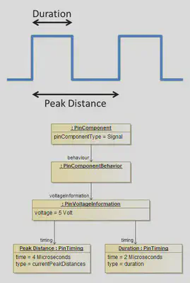
This example shows how a digital signal with pulse width and pulse separation can be defined. The PinComponentBehavior of a PinComponent has PinVoltageInformation. The PinVoltageInformation can define multiple PinTiming definitions. For pulsed digital signals, two PinTimings are used. One PinTiming (Duration) describes the pulse width. The other PinTiming (Peak Distance) describes pulse separation.
Load Type Dependant Maximum Current (Relais)
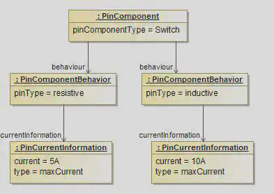
Dependant on the load type (inductive, resistive, capacitive) a switching contact of a relais can have different maximum loads.
The diagram shows a PinComponent of type switch that has two PinComponentBehaviors with pinType resistive and inductive. Each PinComponentBehavior has a PinCurrentInformation with type maxCurrent and different current values.
Topology
Topological Protection Requirements
Background
During geometrical harness design (e.g. in 3D), certain sections of the electrical wiring harness may require additional protection — e.g., increased abrasion resistance or sound damping — due to the local mechanical or environmental conditions at the vehicle.
Modelling Options
In the VEC, there are two relevant modeling approaches to express such requirements or solutions:
- Using a
PartUsageto define Requirements for a wire protection component. - Using a
TopologyZoneto describe conditions and requirements implied by topology elements
This guideline explains when to use which approach and clarifies the validity of zones covering disjoint locations.
PartUsage
A PartUsage represents a placeholder component that must later be realized as a PartOccurrence during detailed design and production preparation. The PartOrUsageRelatedSpecification referenced by the PartUsage express requirements for a wire protection component, that must be satisfied by the PartOccurrence selected later in the process, without defining the actual solution or specific component.
Use this approach when:
- You are already defining the solution for a requirement
- It is known what type of protection will be installed (e.g. tape, tube, sleeve…)
- Placement along segments is already planned
- Properties of the planned protection need to be specified (e.g.
SoundDampingClass,RobustnessProperties,Materialetc.)
Statement expressed:
“A wire protection component will be installed here, and here are its intended characteristics.”
TopologyZone
A TopologyZone represents a spatial condition in the vehicle that imposes requirements on the harness.
Use this approach when:
- You want to express requirements caused by the installation environment
- No specific solution has yet been decided
- The affected topology areas may be intermittent (segments enter or exit the zone)
Examples:
- “Wet zone close to the ground”
- “High-abrasion zone at specific contact points”
- Areas requiring sound damping due to vibration risk
Statement expressed:
“Segments inside this zone must satisfy certain robustness or damping requirements.”
Topology Zone Example
The following section explains how TopologyZones work using a specific example.
A description of the general concepts of topology zone modelling in the VEC can be in found in
Specification, Chapter “Topology Zones”.
The figure below shows a TopologySegment routed through different topology zones in a vehicle.
Each zone represents an area with specific environmental conditions that impose requirements on the wiring harness.
In this example a Hot Zone (red) and a Wet Zone (blue) are defined. The example topology consists of three segments:
SEG-I: Starts atND-Iin no specific zone, then enters the Hot Zone at the locationLoc Aand ends atND-IV, still in the Hot Zone.SEG-II: Starts atND-IVin the Hot Zone and ends atND-IIin no specific zone. It leaves the Hot Zone atLoc B. On its way it passes through the Wet Zone between locationsLoc CandLoc D. BetweenLoc CandLoc Bthe segment is therefore in both zones simultaneously.SEG-III: Located entirely within the Hot Zone.

The assignments of the segments to the zones are modelled using ZoneAssignments. Each assignment defines the relation between a TopologySegment and a TopologyZone. If the TopologySegment is only partially located within the TopologyZone a ZoneCoverage defines the start and end locations of the coverage on the segment. Multiple ZoneCoverages can be defined for one ZoneAssignment to cover disjoint areas of a segment.
The XML snippets in the following sections are taken from a consistent file representing the example above. For better readability, some parts of the XML are omitted. This is indicated by using ... in the XML. The complete VEC file can be downloaded from the Additional Resources at the end of this page.
The definition consists of two relevant specifications: A TopologySpecification and TopologyZoneSpecification for the zones. In this example, both are contained in the same DocumentVersion. The definition of the topology looks as follows:
    ...
    <Specification xsi:type="vec:TopologySpecification" id="TopologySpecification_00002">
      <Identification>TOPOLOGY</Identification>
      <TopologyNode id="TopologyNode_00003">
        <Identification>ND-I</Identification>
      </TopologyNode>
      <TopologyNode id="TopologyNode_00004">
        <Identification>ND-II</Identification>
      </TopologyNode>
      <TopologyNode id="TopologyNode_00005">
        <Identification>ND-III</Identification>
      </TopologyNode>
      <TopologyNode id="TopologyNode_00006">
        <Identification>ND-IV</Identification>
      </TopologyNode>
      <TopologySegment id="TopologySegment_00007">
        <Identification>SEG-I</Identification>
        <EndNode>TopologyNode_00006</EndNode>
        <StartNode>TopologyNode_00003</StartNode>
        <LengthInformation id="SegmentLength_00008">
          <Length id="NumericalValue_00009">
            <UnitComponent>SIUnit_00037</UnitComponent>
            <ValueComponent>1100.0</ValueComponent>
          </Length>
          <Classification>Designed</Classification>
        </LengthInformation>
      </TopologySegment>
      <TopologySegment id="TopologySegment_00010">
        <Identification>SEG-II</Identification>
        <EndNode>TopologyNode_00004</EndNode>
        <StartNode>TopologyNode_00006</StartNode>
        ...
      </TopologySegment>
      <TopologySegment id="TopologySegment_00013">
        <Identification>SEG-III</Identification>
        <EndNode>TopologyNode_00006</EndNode>
        <StartNode>TopologyNode_00005</StartNode>
        ...
      </TopologySegment>
    </Specification>
    ...
The definition of the Zones is the following. The snippet shows the complete definition of the Hot Zone. The definition of the Wet Zone is similar and therefore the assignment section is omitted here (see complete file for a full reference).
For SEG-I and SEG-II the assignment defines a ZoneCoverage to indicate the start and end locations of the coverage on the segment, since they are only partially within in the zone. If those segments had multiple areas where they interacted with the zone, each area would be defined by an individual ZoneCoverage. SEG-III is entirely within the Hot Zone and therefore does not need a coverage definition.
    ...
    <Specification xsi:type="vec:TopologyZoneSpecification" id="TopologyZoneSpecification_00016">
      <Identification>TOPOLOGY-ZONES</Identification>
      <Zone id="TopologyZone_00017">
        <Identification>HOT</Identification>
        <AmbientTemperature id="TemperatureInformation_00018">
          <TemperatureRange id="ValueRange_00019">
            <UnitComponent>SIUnit_00041</UnitComponent>
            <Minimum>-30.0</Minimum>
            <Maximum>125.0</Maximum>
          </TemperatureRange>
          <TemperatureType>AmbientTemperature</TemperatureType>
        </AmbientTemperature>
        <!-- SEG-I is partially within the Hot Zone, from Loc A to ND-IV -->
        <Assignment id="ZoneAssignment_00018">
          <AssignedSegment>TopologySegment_00007</AssignedSegment>
          <Coverage id="ZoneCoverage_00019">
            <FirstLocation xsi:type="vec:NodeLocation" id="NodeLocation_00020">
              <Identification>ND-IV</Identification>
              <ReferencedNode>TopologyNode_00006</ReferencedNode>
            </FirstLocation>
            <SecondLocation xsi:type="vec:SegmentLocation" id="SegmentLocation_00021">
              <Identification>Loc A</Identification>
              <Offset id="NumericalValue_00022">
                <UnitComponent>SIUnit_00037</UnitComponent>
                <ValueComponent>600.0</ValueComponent>
              </Offset>
              <Anchor>FromEndNode</Anchor>
              <ReferencedSegment>TopologySegment_00007</ReferencedSegment>
            </SecondLocation>
          </Coverage>
        </Assignment>
        <!-- SEG-II is partially within the Hot Zone, from ND-IV to Loc B -->
        <Assignment id="ZoneAssignment_00023">
          <AssignedSegment>TopologySegment_00010</AssignedSegment>
          <Coverage id="ZoneCoverage_00024">
            <FirstLocation xsi:type="vec:NodeLocation" id="NodeLocation_00025">
              <Identification>ND-IV</Identification>
              <ReferencedNode>TopologyNode_00006</ReferencedNode>
            </FirstLocation>
            <SecondLocation xsi:type="vec:SegmentLocation" id="SegmentLocation_00026">
              <Identification>Loc B</Identification>
              <Offset id="NumericalValue_00027">
                <UnitComponent>SIUnit_00037</UnitComponent>
                <ValueComponent>500.0</ValueComponent>
              </Offset>
              <Anchor>FromStartNode</Anchor>
              <ReferencedSegment>TopologySegment_00010</ReferencedSegment>
            </SecondLocation>
          </Coverage>
        </Assignment>
        <!-- SEG-III is entirely within the Hot Zone -->
        <Assignment id="ZoneAssignment_00028">
          <AssignedSegment>TopologySegment_00013</AssignedSegment>
        </Assignment>
      </Zone>
       <Zone id="TopologyZone_00031">
        <Identification>WET</Identification>
        <RequiredRobustnessProperties id="RobustnessProperties_00032">
          <Class>LiquidIngressProtection</Class>
          <ClassKey>9K</ClassKey>
          <ClassReferenceSystem>ISO 20653</ClassReferenceSystem>
          <HasRobustness>true</HasRobustness>
        </RequiredRobustnessProperties>
        ...
      </Zone>
      ...
    </Specification>
    ...
Placements and Dimensions
A Placement defines the way how a component is associated to the topology. The following sections contain examples about the different types of placements.
Semantic Difference: SegmentLocation vs. NodeLocation
Disclaimer: This page or section is currently under review by the community.
The content of this page or section can be subject to change at any time. If you find any issues or if you have any review comments please drop us an issue in our Issue Management on GitHub.
This page or section resolves #935
The VEC has two different concepts to define locations in the topology: SegmentLocation and NodeLocation. On the first glance it seems that there is a semantic overlap between these two concepts, since a TopologySegment starts and ends at a TopologyNode, so where is the difference between a SegmentLocation with an offset of 0mm (or a value equal to the segment length) and a NodeLocation at the corresponding TopologyNode? The figure below illustrates the scenario:

A SegmentLocation is used to define a location somewhere “on” a TopologySegment, even if it is at the very beginning or end of the segment. This means that the location has a clear reference to a specific single segment. This is especially important, if mulitple segments are connected to the same node (e.g. a branching point). In this case a SegmentLocation with an offset of 0mm or segment length clearly defines on which segment the location is placed. In contrast a NodeLocation always refers to the TopologyNode itself, without any reference (or preference) to a specific segment. This means that a NodeLocation is used, if the location is really “at” the node, independent of the connected segments.
SegmentLocations for component whe the placement has a clear association to specific TopologySegment, even if the location is (infinitesimal) close to a TopologyNode. Use NodeLocations for components which are really placed “at” a TopologyNode, independent of the connected segments.Placement on Areas (Wire Protection)
One common use case when placing components in the topology is the covering of specific area of the wiring harness with that component, either for protection or cohesion (e.g. a tubing, spiral wrap, or tape). The following sections illustrate how such placements can be modelled in the VEC, both without and with dimensions.
Basic Wire Protection

This diagram illustrates the placement of a basic wire protection as shown in next diagram.
Please note that the depiction of the TopologyNodes is for visualization purposes only. In the logical topology model of the VEC, they do not have any spatial extent. For this reason, both the dimensions and the SegmentLocation are shown at the center of the node (i.e. at the end of the TopologySegment).

The figure above illustrates the placement of a basic wire protection. The PartOccurrence is placed using an OnWayPlacement via a PlaceableElementRole, meaning that the component covers a linear section of the harness topology. The start and end of this protected area are defined by two Locations.
Since a wire protection is, from a semantic point of view, inherently associated with a TopologySegment, it is typically placed using SegmentLocations rather than a NodeLocation. This becomes particularly relevant at TopologyNodes where multiple segments meet: a NodeLocation would not clearly express which segment the protection refers to (see also the section “Semantic Difference: SegmentLocation vs. NodeLocation”).
In the shown example, the EndLocation is a SegmentLocation located on a TopologySegment at an offset of 120 mm measured from the StartNode. The StartLocation is also defined by a SegmentLocation at the opposite end of the same segment.
It is important to note that the choice of the Anchor in a SegmentLocation carries a distinct semantic meaning. For instance, the start location in the diagram can be expressed either by Offset = 0 with Anchor = "FromEndNode" or equivalently by Offset = SegmentLength = 120 mm with Anchor = "FromStartNode". While both variants yield the same geometric position in the current state of the product, their engineering semantics differ significantly.
In the representation used in the figure, the two locations refer to different reference nodes (one to the start node, the other to the end node). This decouples the definition of the protected area from the absolute segment length and ensures that the complete segment (minus the defined offsets) is always covered, even if the segment length changes. If, in contrast, both locations were defined relative to the same reference node (e.g. both with Anchor = "FromStartNode"), the protected region would be spatially fixed and would not adapt to changes in the segment length.
StartLocation and an EndLocation in the OnWayPlacement, the placement does not imply any directionality of the placed component along the topology. The two roles of start and end are solely used to identify the locations unambigiously. It could have been named differently as well (e.g. LocationA and LocationB), without changing the semantics of the placement. For component types where direction matters (e.g. windings, tapings), additional attributes or relationships within the corresponding roles are used to define the orientation of the component along the topology (see for example the attribute TapingDirection in the class TapeRole).Wire Protection with Dimension

The illustration above extends the previous example by adding a Dimension. In the earlier example, the EndLocation of the wire protection was defined using a tolerance value. This approach can be applied if the tolerance is specified with respect to the adjacent TopologyNode (i.e. the StartNode or EndNode of the TopologySegment).
In most cases, however, the purpose of dimensions is to define measurable quality characteristics. To make them verifiable, they must refer to points that are physically perceptible and measurable on the actual product. In the illustration above, this is not the case for the topology node ND-2, since it is not recognizable in the end product (all wires pass through and no component is located there). In contrast, ND-3 is physically identifiable, as a branching occurs in the harness at this point. The green dimension therefore specifies that the valid distance from this branching point to the start of the wire protection shall be 220 mm with a tolerance of ±20 mm.

The placement of the WireProtection is identical to that in the previous example and is now extended by a Dimension (highlighted in green). This Dimension specifies a tolerance of ±20 mm between the TopologyNode ND-III and the beginning of the WireProtection. The tolerance is explicitly defined in this dimension in order to avoid tolerance accumulation in dimension chains.
The fact that the Dimension is defined between the TopologyNode and the start of the WireProtection is expressed by directly referencing the TopologyNode via a contained NodeLocation. The SegmentLocation used as the DimensionAnchor is identical to the one used for the placement of the WireProtection, thereby ensuring a consistent geometric and semantic reference.
The flag ValueCalculated = true of the Dimension indicates that the ValueComponent (220 mm) is a derived and calculated value rather than a user-defined one. It can be obtained from the placement information in combination with the lengths of the corresponding TopologySegments.
Wire Protection covering multiple Topology Segments
In some cases it is necessary to place a wire protection over a greater area of the topology, consisting of more than one TopologySegment (e.g. Tubes with a fixed length). This is illustrated in the following example:

In the VEC such a wire protection is modelled with a OnWayPlacement. The StartLocation and EndLocation are defined similar to the previous examples. The difference is that a Path is defined for the way inbetween the locations, that can cover multiple TopologySegments. This is illustrated in the next diagram:

The Path is an ordered list of the segments from the start to the end. If a SegmentLocation is used for the start and/or the end, the path must contain these TopologySegments as well.
Placement on Points
The other common use case when placing components in the topology is the placement of components fixed to specific points in the topology, such as connectors, fixings, and so on. The following sections illustrate how such placements can be modelled in the VEC, both without and with dimensions.
For components that are placed on specific points, the Placement defines an association of a reference point on the component (the PlacementPoint) to a specific point in the topology (the Location). The exact postion of the PlacementPoint on the component is defined in the components PlaceableElementSpecification. For most components types specific conventions exists, which point on the component is used as PlacementPoint.
Single Locations
The most common case for point-based placement is the assignment of a component to a single Location. Such components can be placed either on a TopologyNode or on a TopologySegment. Depending on the component type, additional constraints may apply. For example, connectors shall only be placed on topology nodes; placing them on a segment would imply a wire ending in the middle of the segment, which would violate the definition of a TopologySegment. The following figure illustrates these concepts:

The diagram below illustrates the instantiation of the example in the preceding diagram.

As shown in the figure above, the PartOccurrence is placed using an OnPointPlacement that references the a PlaceableElementRole of the PartOccurrence. The location where it is placed is defined by a single Location. For components that are placed on a TopologySegment, a SegmentLocation is used. For components that are placed on a TopologyNode, a NodeLocation is used.
The explicit definition of the PlacementPoints in the PlaceableElementSpecification and the PlacementPointReference in the PlaceableElementRole is not mandatory for components that are only placed at a single location. However, it is recommended to define them anyway, as it improves the clarity of the model and allows for easier extension in the future (e.g. if the component is later placed at multiple locations).
Multiple Locations with Dimensions
In addition to simple placements at single locations, significantly more complex scenarios also exist. One such scenario is illustrated in the following figure.

The figure shows a bracket featuring two guides through which two TopologySegments can pass. These guides are represented by the placement points A and C. In the shown example, the bracket is positioned in the topology by assigning these placement points to SEG-1 and SEG-2 using SegmentLocations.
For quality assurance, however, the decisive measure is the distance between a reference point in the topology (in this case the TopologyNode ND-2) and another functionally significant point of the bracket, for example the pin by which the bracket is fixed to the vehicle body. This point is not relevant for establishing the connection to the topology and is therefore not used as a placement point. Instead, it is defined as a MeasurementPoint . In the figure, this point is labeled as MeasurementPoint B. The dimension indicated in green specifies the required distance between this measurement point and the TopologyNode ND-2, along with the associated tolerance.
For this example, a bracket is used. However, similar scenarios can also arise with other component types, such as connectors, grommets or cable ducts that have multiple connection points to the topology and additional functionally relevant points that need to be dimensioned. The nature of those points can vary depending on the component type. For instance, in connectors, the SegmentConnectionPoints are used as placement points, while for grommets, the CableLeadThroughOutlets serve this purpose.
The following diagram illustrates the instantiation with VEC classes of the example in the preceding diagram.

Please note that the actual definition of the PlacementPoints and MeasurementPoints is done in the PlaceableElementSpecification of the part master definition (not shown in the diagram for clarity). The PlacementPointReferences A and C in the PlaceableElementRole create the relationship between the placement points defined in the component specification and the locations in the topology. The MeasurementPointReference B in the PlaceableElementRole creates the relationship between the measurement point defined in the component specification and the dimension defined in the placement.
It can also be seen, that the ValueCalculated-attribute of Dimension is set to false, indicating that the dimension value is explicitly defined. Since a MeasurementPoint is an arbitrary point on the component the dimension value can not be derived from topology and placement information alone.
Default Dimensions

The diagram illustrates the use of a DefaultDimensionSpecification. The DefaultDimensionSpecification can be used to specify default dimensions / tolerances for certain attributes and ValueRanges. In this examples the Specification is used for the length of wires. (indicated by the dimensionType). The dimensionValueRange defines for which value’s of this type, the referenced Tolerance is applicable.
In this example for a wire length lower than 250 mm a Tolerance of +5 mm is allowed, for values between 250 mm and 500 mm a Tolerance of +10 mm is allowed and for everything above 500 mm a Tolerance of 15 mm is allowed.
Routing
A Routing is used to associate a RoutableElement with a topology. For a wiring harness,
the RoutableElement will be a WireElementReference. In early development phases
(and depending on the development process) it might be desired to associate a schematic with a topology. Therefore,
Connections are also RoutableElement.
In this implementation guideline WireElementReferences will be used throughout. However, the same principles would apply
when you define Routings for Connections. The following sections are based on a consistent example that
can be downloaded from the Additional Resources at the end of this page.
Foundation / Input Data
A routing is defined as a directed path through the topology of a wiring harness. The RoutingSpecification is a
container for individual Routings that belong to the same context, e.g. all wires of a harness. The Routing
stores the results of a routing algorithm and is independent from the actual routing strategy. However, a requirement was, to be able to store
constraints on the routing and inputs that led to the result, in order to support a re-routing based on the data in the VEC (e.g. during implementation of topology changes).
The simplest possible routing algorithm searches for a loop-free path between the endpoints of a wire. If this does not yield
a unique result, additional guidance is required. This guidance can either be defined by the user or derived from additional information
(e.g., configuration constraints). The corresponding result can then be stored in the mandatorySegments of the Routing.
This is a list of TopologySegment that the routing algorithm shall pass through as intermediate targets.
The following subsections describe the required input for any routing algorithm and its mapping in the VEC.
Topology
The following figure depicts the topology that serves as foundation for this implementation guideline.

The representation in the VEC is the following:
<Specification xsi:type="vec:TopologySpecification" id="TopologySpecification_00023">
  <Identification>TOPOLOGY</Identification>
  <TopologyNode id="TopologyNode_00024">
    <Identification>ND-1</Identification>
  </TopologyNode>
  <TopologyNode id="TopologyNode_00025">
    <Identification>ND-2</Identification>
  </TopologyNode>
  ...
  <TopologySegment id="TopologySegment_00032">
    <Identification>SEG-2</Identification>
    <EndNode>TopologyNode_00025</EndNode>
    <StartNode>TopologyNode_00024</StartNode>
  </TopologySegment>
  ...
</Specification>
PartOccurrences
A CompositionSpecification contains the required PartOccurrences. The example consists of three connectors (A1, A2, A3) and three wires (W1, W2,W3).
<Specification xsi:type="vec:CompositionSpecification" id="CompositionSpecification_00075">
  <Identification>COMPONENTS</Identification>
  <Component id="PartOccurrence_00076">
    <Identification>A1</Identification>
    <Role xsi:type="vec:PlaceableElementRole" id="PlaceableElementRole_00077">
      <Identification>A1</Identification>
      <PlaceableElementSpecification>PlaceableElementSpecification_00003</PlaceableElementSpecification>
    </Role>
    <Role xsi:type="vec:ConnectorHousingRole" id="ConnectorHousingRole_00078">
      <Identification>A1</Identification>
      <ConnectorHousingSpecification>ConnectorHousingSpecification_00004</ConnectorHousingSpecification>
      <SlotReference xsi:type="vec:SlotReference" id="SlotReference_00079">
        <Identification>A</Identification>
        <ReferencedSlot>Slot_00005</ReferencedSlot>
        <CavityReference id="CavityReference_00080">
          <Identification>1</Identification>
          <ReferencedCavity>Cavity_00006</ReferencedCavity>
        </CavityReference>
      </SlotReference>
    </Role>
    <Part>PartVersion_00106</Part>
  </Component>
  ...
  <Component id="PartOccurrence_00091">
    <Identification>W1</Identification>
    <Role xsi:type="vec:WireRole" id="WireRole_00092">
      <Identification>W1</Identification>
      <WireSpecification>WireSpecification_00014</WireSpecification>
      <WireElementReference id="WireElementReference_00093">
        <Identification>W1</Identification>
        <ReferencedWireElement>WireElement_00015</ReferencedWireElement>
        <WireEnd id="WireEnd_00094">
          <Identification>A1.1</Identification>
          <PositionOnWire>0.0</PositionOnWire>
        </WireEnd>
        <WireEnd id="WireEnd_00095">
          <Identification>A2.1</Identification>
          <PositionOnWire>1.0</PositionOnWire>
        </WireEnd>
      </WireElementReference>
    </Role>
    <Part>PartVersion_00107</Part>
  </Component>
  ...
</Specification>
Placements of Connectors
The connectors are placed with OnPointPlacements in the toplogy (compare the figure above).
<Specification xsi:type="vec:PlacementSpecification" id="PlacementSpecification_00040">
  <Identification>PLACEMENTS</Identification>
  <Placement xsi:type="vec:OnPointPlacement" id="OnPointPlacement_00041">
    <Identification>A1</Identification>
    <PlacedElement>PlaceableElementRole_00077</PlacedElement>
    <Location xsi:type="vec:NodeLocation" id="NodeLocation_00042">
      <Identification>A1</Identification>
      <ReferencedNode>TopologyNode_00024</ReferencedNode>
    </Location>
  </Placement>
  ...
</Specification>
Connectivity
The connectivity of the wires is defined as follows with ContactPoints.
| Wire | From | To |
|---|---|---|
W1 | A1 | A2 |
W2 | A1 | A3 |
W3 | A1 | A2 |
<Specification xsi:type="vec:ContactingSpecification" id="ContactingSpecification_00056">
  <Identification>HARNESS-1</Identification>
  <ContactPoint id="ContactPoint_00057">
    <Identification>A1.1</Identification>
    <CavityMounting id="CavityMounting_00058">
      <EquippedCavityRef>CavityReference_00080</EquippedCavityRef>
    </CavityMounting>
    <WireMounting id="WireMounting_00059">
      <ReferencedWireEnd>WireEnd_00094</ReferencedWireEnd>
    </WireMounting>
  </ContactPoint>
  ...
</Specification>
Routing
Basic Routing
The simplest routing case is a direct, loop-free and unambiguous routing. In this case, the wire takes the direkt path through the topology, each segment is only passed once and there is only one valid path.
In our example, this is the case for W1 going from A1 to A2 through SEG-2 and SEG-1.
<Routing id="Routing_00048">
  <Identification>W1</Identification>
  <RoutedElement>WireElementReference_00093</RoutedElement> <!-- W1 -->
  <Path id="Path_00049">
    <Segment>TopologySegment_00033 TopologySegment_00032</Segment> <!-- SEG-1, SEG-2 -->
  </Path>
</Routing>
Remarks
- The segment list in the routing is ordered and the order is relevant. Especially for the more complex cases following, it is relevant in which order the segments are visited. However, the direction is not relevant, as there is no semantic meaning defined for the direction of wires. So a routing (
A,B,C) is semantically equivalent to a routing (C,B,A). - Since order matters, a routing that does not go through adjacent segments in correct order is not valid. So, based on our example, a routing containing the following path …,
SEG-1,SEG-4,SEG-3,SEG5, … is considered invalid, as there is “gap” in the topology betweenSEG-1&SEG-4, missingSEG-3and after that, the routing is jumping back and forth. As a result, the routing might contain all segments required for a complete path, but not in the correct order and therefore is invalid.
Ambiguous Routing
In our example, the wire W2 is a connection between A1 and A2. From A1 to A2 there are two direct, loop-free paths. One taking SEG-7 and SEG-8 (hereafter referred to as path X) and the other one via SEG-4 and SEG-5 (path Y). Which path the wire W2 should take is a design descision. To document the resulting routing, a simple routing as shown in the section before would be sufficient.
However, in case of changes, the routing could not be recalculated. Therefore it is possible to document the engineers design descision in addition to the actual routing result:
<Routing id="Routing_00052">
  <Identification>W2.1</Identification>
  <MandatorySegment>TopologySegment_00035 TopologySegment_00036</MandatorySegment> <!-- SEG-4 & SEG-5 -->
  <RoutedElement>WireElementReference_00098</RoutedElement>
  <Path id="Path_00053">
    <Segment>TopologySegment_00032 TopologySegment_00034 TopologySegment_00035 TopologySegment_00036 TopologySegment_00037</Segment>
    <!-- SEG-2, SEG-3, SEG-4, SEG-5, SEG-6 -->
  </Path>
</Routing>
The Path represents the result of the routing, the MandatorySegment property defines the TopologySegments that are mandatory to be visited by the routing algorithm, in order to resolve the ambiguity.
Routing Variants
There are use cases where it is desired to have routing variants for a single RoutableElement, that are valid under certain conditions. This can be the case, when a RoutableElement represents an abstract concept like a Connection or a WireElementReference from a wiring definition. Those could be routed through through different geometric variants, and could be used then, in the further developlment provess, to derive specific wire variants in a harness. This feature of the model could also used to represent packaging variants of an actual harness. However, the development process has to ensure, that the harness actually “fits” into all packing variants (e.g. the different routings variants should result in the same wire length).
The example contains routing variants for the wire W2. There is the routing variant W2.1 which has been already used for the “Ambiguous Routing” example above. The example contains and additional routing W2.2 that takes path X (via SEG-7, SEG-8).
<Routing id="Routing_00054">
  <Identification>W2.2</Identification>
  <MandatorySegment>TopologySegment_00038 TopologySegment_00039</MandatorySegment>
  <!-- SEG-7, SEG-8-->
  <RoutedElement>WireElementReference_00098</RoutedElement>
  <Path id="Path_00055">
    <Segment>TopologySegment_00032 TopologySegment_00034 TopologySegment_00038 TopologySegment_00039 TopologySegment_00037</Segment>
  </Path>
</Routing>
Both Routings reference the WireElementReference W2 as RoutedElement. The conditions under which each routing is valid are defined with a VariantConfigurationSpecification and a ConfigurationConstraintSpecification. The VariantConfigurationSpecification defines the conditions itself. In this case an option RL for right-hand drive and LL for left-hand drive.
<Specification xsi:type="vec:VariantConfigurationSpecification" id="VariantConfigurationSpecification_00017">
  <Identification>VARIANTS</Identification>
  <VariantConfiguration id="VariantConfiguration_00018">
    <Identification>RL</Identification>
    <LogisticControlExpression>RL</LogisticControlExpression>
  </VariantConfiguration>
  <VariantConfiguration id="VariantConfiguration_00019">
    <Identification>LL</Identification>
    <LogisticControlExpression>LL</LogisticControlExpression>
  </VariantConfiguration>
</Specification>
The ConfigurationConstraintSpecification is used to apply the VariantConfigurations as constraints to specific model elements.
<Specification xsi:type="vec:ConfigurationConstraintSpecification" id="ConfigurationConstraintSpecification_00020">
  <Identification>CONFIG_CONSTRAINTS</Identification>
  <ConfigurationConstraint id="ConfigurationConstraint_00021">
    <Identification>RL</Identification>
    <ConfigInfo>VariantConfiguration_00018</ConfigInfo>
    <ConstrainedElements>TopologySegment_00035 TopologySegment_00036 Routing_00052</ConstrainedElements>
  </ConfigurationConstraint>
  <ConfigurationConstraint id="ConfigurationConstraint_00022">
    <Identification>LL</Identification>
    <ConfigInfo>VariantConfiguration_00019</ConfigInfo>
    <ConstrainedElements>TopologySegment_00038 TopologySegment_00039 Routing_00054</ConstrainedElements>
  </ConfigurationConstraint>
</Specification>
It can be seen, that in this case the same contraints are applied to the topology segments and the routings using those segments. This inidicates, that the ConfigurationConstraints control the existence of parts of the topology available to the routing algorithm. Those conditions are then inherited by the derived routings.
However, this is just a logical implication of the example. There might be others reason for routing variants, or the relationship between the variant conditions of the different variantes might be more complex.
Forced Routing
There are use case, where the routing of a wire should not take a direct path in the topology, but a specifically desgined one. For example a wire should go through an emergency disconnect location, which is a diversion from the direct path and might require going back an forth through the same segments. This is represented in a similiar way as resolving ambigious routings with MandatorySegments.
In the example, the wire W3 is forced through SEG-3. Defining a mandatory segment, means that the wire has to be routed from its start location through the mandatory segment(s) at least once. After that, the routing has to find a way to the destination, which might require to visit the mandatory segment again.
To mark this routing as specifically designed, it can be flaged as SpecialRouted, meaning an automatic rerouting is not allowed. Additionally a human readable comment for the reason of the “special routing” can be provided.
<Routing id="Routing_00050">
  <Identification>W3</Identification>
  <SpecialRoutedComment id="LocalizedString_001">
    <LanguageCode>En</LanguageCode>
    <Value>Emergency Disconnect</Value>
  </SpecialRoutedComment>
  <SpecialRouted>true</SpecialRouted>
  <MandatorySegment>TopologySegment_00034</MandatorySegment>
  <RoutedElement>WireElementReference_00103</RoutedElement>
  <Path id="Path_00051">
    <Segment>TopologySegment_00033 TopologySegment_00034 TopologySegment_00034 TopologySegment_00032</Segment>
  </Path>
</Routing>
Compliance Tests
A key objective of data exchange standards in general, and the VEC (Vehicle Electric Container) standard in particular, is to ensure system interoperability and guarantee the accurate interpretation of information. To achieve this, specifications must be as precise as possible, with minimal ambiguity. However, informal definitions are often easily overlooked. Compliance with the rules can only be ensured through formal definitions, which allow for automated, fast, and simple checks across systems.
Current XML schema definitions of the VEC are only effective for verifying the basic syntactic structure. They cannot account for more complex rules, dependencies, or logical relationships. The compliance tests aim to address this gap. By introducing the VEC ontology, the standard gains access to Semantic Web technologies. With these technologies it is possible to formalize previously informal aspects of the VEC specification, reducing potential misinterpretations.
This is an ongoing process, with the rules in the validation suite continually adapted and expanded. Feedback and suggestions for further rule enhancements are highly encouraged.
How it Works
The VEC Compliance Test Suite leverages the VEC ontology, which has been published alongside the model and XML schema since 2024, and consists of several components.
Extensions to the VEC Ontologie
The vec-general-onto.ttl file defines elements and axioms that extend the VEC ontology derived directly
from the VEC Model. These definitions primarily aim to simplify rules and queries within the
compliance test suite. If these extensions prove useful and provide broader benefits,
they may be incorporated into the official VEC ontology at a later stage.
An example of these extensions is the generalization of all VEC elements that have functional keys
(see the example below). These definitions ensure that any element with an identification property
is classified as vec:Identifiable. This allows us to create a general rule
(e.g., for the uniqueness of identifications) for all identifiable elements.
vec:Identifiable a owl:Class .

vec:identification
    rdf:type owl:DatatypeProperty ;
    rdfs:domain vec:Identifiable .

vec:abstractSlotSlotNumber
    rdfs:subPropertyOf
        vec:identification .

vec:contactPointIdentification
    rdfs:subPropertyOf
        vec:identification .

....
Semantic Rules
The vec-general-shacl.ttl file defines SHACL(Shapes Constraint Language) rules that can not be
derived directly from the UML model of the VEC1. These rules are currently informally specified in the VEC specification or
Implementation Guidelines. Each rule includes a custom message containing a rule/test case number (e.g., TC-0001), which
corresponds to an identifier found in the Compliance Rules.
vecsh:ToleranceShape rdf:type sh:NodeShape ;
    sh:targetClass vec:Tolerance ;
    sh:property
        [
            sh:path vec:toleranceLowerBoundary ;
            sh:lessThanOrEquals vec:toleranceUpperBoundary ;
            sh:message "TC-0001: 'Tolerance.LowerBoundary' must be less than or equals 'UpperBoundary'."@en
        ] .
Queries
The VEC defines several extension points (e.g., custom properties) for addressing individual requirements or system- and process-specific data. However, these elements are also prone to misuse. Determining whether a particular extension element has been used correctly or incorrectly often requires careful assessment. To assist with this, the Compliance Test Suite includes a set of queries that provide information about the extensions used, as well as their context and content. These queries allow for quick and easy manual evaluation of how extensions have been used.
Execution
All components of the Compliance Test Suite can be downloaded via the link at the bottom of this page. There are two main ways to execute the Compliance Test Suite:
- All elements (Ontology Extension, Semantic Rules, and Queries) can be used in any RDF environment that supports the relevant technologies. However, this requires the VEC data to be available in an RDF format to validate it within that environment.
- For easier validation of VEC
XMLdata, you can use 4Soft’s VEC RDF Toolkit, available for free download here. This tool uses the suite definition provided below, runs it on a set of VEC XML files, and generates an Excel report with the results.
Compliance Rules
The table below lists all rules currently contained within the Compliance Test Suite. The set of rules will be continiously extended, so be sure to revisit frequently.
| # | Target Class | Description | Published | Updated |
|---|---|---|---|---|
| TC-0001 | Tolerance | Tolerance.LowerBoundary must be less than or equals UpperBoundary | 18.09.2024 | 18.09.2024 |
| TC-0002 | ValueRange | ValueRange.Minimum must be less than or equals Maximum | 18.09.2024 | 18.09.2024 |
| TC-0003 | PartVersion | To avoid ambiguity, a PartVersion shall be only described by at most one Specification of each type. | 18.09.2024 | 18.09.2024 |
| TC-0004 | PartVersion | If a PartVersion is describedBy PartOrUsageRelatedSpecifications there shall be one corresponding to the PrimaryPartType. | 18.09.2024 | 18.09.2024 |
| TC-0005 | DocumentVersion | Having multiple DocumentVersion with the same documentNumber is suspicious, even when the documentVersion is different. | 18.09.2024 | 18.09.2024 |
| TC-0006 | DocumentVersion | The documentNumber shall not be /NULL | 18.09.2024 | 18.09.2024 |
| TC-0007 | PartVersion | The partNumber shall not be /NULL | 18.09.2024 | 18.09.2024 |
| TC-0008 | Identifiable | identifications must be unique within a containment. | 18.09.2024 | 18.09.2024 |
| TC-0009 | OccurrenceOrUsage | An OccurrenceOrUsage shall define at most on Role per specific type. | 18.09.2024 | 18.09.2024 |
Rules derived from the UML model are included in the SHACL schema published with each version of the VEC. ↩︎