Component Description
Change History
| Id | Subject | Date |
| Latest Commit | Update Guidelines for GrippingFeatures (#1163) | 2026-09-22 |
| #1163 | Added gripping features for handling automation. | 2026-09-22 |
| KBLFRM-931 | Clarification of the Minimum Content of DocumentVersions for Part Master Data. | 2022-09-12 |
This section explains the concepts for the representation of part master data and component specifications in the VEC. For a general explanation of the terms, see the parent section Product Definition. If you search information about specific component types e.g. wires, connectors etc. see Component Types
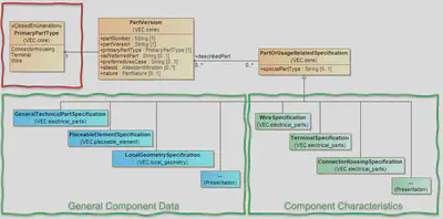
Due to the various supported use cases, the VEC’s concept for component specifications is designed modular. The figure above contains the most relevant elements
Note: The picture is for illustration purpose only and is taken from a current VEC version at the time of writing. The classes, attributes etc. might have changed in the mean time.
The unique identification of a component is its PartVersion. It is serves as an identifier and contains only additional PDM information like Approval,Creation or ChangeDescription. The actual description of the properties of a component is done via PartOrUsageRelatedSpecifications, whereby each specification covers only a certain aspect of the component. A holistic description of a component is a combination of multiple specifications, but no more than one of a specific specification type at a time. Those specifications can be divided into two groups:
General Component Data: Specifications in this group describe general properties of components that are applicable to all or at least a large group of components. For example:
GeneralTechnicalPartSpecificationfor common properties like weight or material for all component types.PlaceableElementSpecificationfor components that have an explicitly defined position in the harness topology lik wire protections, connectors or fixings.LocalGeometrySpecificationfor information about the component’s geometry model, e.g. the bounding box, transformations, segment connection points.
Component Characteristics: Specifications in this group describe properties that are very specific for a certain component type, e.g.
WireSpecificationfor wires orConnectorHousingSpecificationfor connectors. In most cases, a part can be clearly assigned to one of these categories. However, there can be cases of “hybrid” components that fall into more than one category. In this case, thePrimaryPartTypedefines the primary character of the components. A detailed description can be found here: “Description of Parts”.
Unclassified / Custom Component Types
The VEC natively supports a wide range of component types and attributes for them. Nevertheless, this list is probably not exhaustive when considering which component types could potentially appear in the BOM of a wire harness and could also be added by future developments.
Currently, the list of directly supported types is derived from the specific requirements of the VEC and is focused on those components that have a specific relationship with other components in the harness (e.g. wires/connectors) and whose attributes play a strong role in the selection processes during development.
However, following its principle of openness and extendability, the VEC provides a possibility to add such components, that are not specifically supported by it, in a defined way as user/process defined components. The necessary elements to do this are:
- The
PrimaryPartTypeto use isOther. - “General Component Data” can be added with corresponding specifications analogous to a regular component (see above).
- The “Component Characteristics” is expressed by an instance of
PartOrUsageRelatedSpecificationitself (no subclass). - The concrete type of the component (for regular components expressed by the PrimaryPartType), is defined in the
PartOrUsageRelatedSpecification.SpecialPartType-Attribute. - Specific attributes of the “new” type (not available via “General Component Data”) can be added as
CustomPropertyto thePartOrUsageRelatedSpecification. - Instancing is done via a
SpecificRole(see chapter “Instances of undefined Components” in the Specification for Details).
An example in XML of such a custom component can be found in the XML Listings section at the end of this page.
Gripping Features
GrippingFeature and the attribute
GeneralTechnicalPartSpecification.SupportedGrippingFeatures were introduced
with version 2.3.The handling of components in an automated assembly process (e.g. by a robotic gripper) requires that the gripper can engage the component reliably. Standards such as DIN 72036 therefore require components - connector housings in the first place, but grommets, covers or fixings just as well - to provide standardized geometries for the form-fitting gripping during handling and mating processes.
Since this is a property of any component and not of a specific component type, it is part of the “General Component Data” and described with the SupportedGrippingFeatures of the GeneralTechnicalPartSpecification. A GrippingFeature is identified by a Key, whose meaning is defined by a ReferenceSystem - the same pattern that is used for Material or Color (see Physical Properties).
Material or Color, the values of
SupportedGrippingFeatures are not alternative representations of one and the same value.
They are the set of features the component actually provides. A component may therefore declare
several entries for the same ReferenceSystem, as long as their Key values differ. The combination
of ReferenceSystem and Key must be unique.It can be assumed that two components declaring the same Key in the same ReferenceSystem can be handled by the same gripper. This is what makes the information usable for a variance analysis: counting the distinct ReferenceSystem / Key combinations over all components of a harness yields the number of different grippers a production line has to provide.
If a component supports no standardized gripping geometry at all, the attribute is simply absent. There is no dedicated “no gripping feature” value - an empty list is not distinguishable from “not specified”, which is the regular VEC behaviour for optional information (see Content Requirements).
Reference Systems for Gripping Features
The ReferenceSystem is a free string, so the same standard can be written down in different ways. For the variance analysis described above to work across suppliers, the spelling has to be agreed upon. The following values should be used:
| Reference System | Value of ReferenceSystem |
|---|---|
| DIN 72036 | DIN 72036 |
| A company specific system | The company name, consistent with its usage for Color and Material (e.g. ACME Inc.) |
XML Listing
The listing below shows a connector housing that supports two different gripping features of the same reference system and one company specific feature. The gripping features are located in the GeneralTechnicalPartSpecification, the connector specific data in the ConnectorHousingSpecification. Both describe the same PartVersion.
<DocumentVersion id="id_00001">
    <DocumentType>PartMaster</DocumentType>
    <ReferencedPart>id_part_4711</ReferencedPart>
    <Specification xsi:type="vec:GeneralTechnicalPartSpecification" id="id_gtps_1">
        <Identification>GTPS_4711</Identification>
        <DescribedPart>id_part_4711</DescribedPart>
        <SupportedGrippingFeatures id="id_gf_1">
            <Key>AR-1</Key>
            <ReferenceSystem>DIN 72036</ReferenceSystem>
            <Description>
                <LanguageCode>en</LanguageCode>
                <Value>Automation rib, type 1</Value>
            </Description>
        </SupportedGrippingFeatures>
        <SupportedGrippingFeatures id="id_gf_2">
            <Key>AR-3</Key>
            <ReferenceSystem>DIN 72036</ReferenceSystem>
        </SupportedGrippingFeatures>
        <SupportedGrippingFeatures id="id_gf_3">
            <Key>GRP-A</Key>
            <ReferenceSystem>ACME Inc.</ReferenceSystem>
        </SupportedGrippingFeatures>
    </Specification>
    <Specification xsi:type="vec:ConnectorHousingSpecification" id="id_chs_1">
        <Identification>CHS_4711</Identification>
        <DescribedPart>id_part_4711</DescribedPart>
    </Specification>
</DocumentVersion>
PartMaster - DocumentVersions

A part master document describes the properties of a component or a group of
components (a PartVersion or a set of
PartVersions). It can be recognised with the DocumentType = PartMaster. A schematic illustration can be found in the figure on the right side. It contains some general purpose specifications (highlighted in light blue) and component characteristics (highlighted in strong green), in most cases one. Those specifications are not mandatory and only necessary if the corresponding information aspect is relevant in the use case and can be provided.
Additionally, the document could contain auxillary specifications that are
required for a complete component description (in the illustration the
CavitySpecification and SlotSpecification highlighted in light green).
The emphasis here is on “could”, as this is a quite common case,
but a process-specific interpretation of component definitions. For example, if the cavity system is
described and released together with the connector (in the same document), it
makes sense that the corresponding specification is included in the same
DocumentVersion. However, if the cavity system is defined and released
independently, i.e. in a separate document, and used by multiple connectors, it
would be appropriate to place it in its own DocumentVersion
and reuse the information in the document of the connectors (see Reuse of
Documents).
Content Requirements
In an omniscient view of the world, it would be possible to formulate logical constraints and minimum requirements for the content of a PartMaster-Document, such as mandatory content or a logical relationship between the PrimaryPartType and the types of descriptive specifications that have to be used. For example, it could be stated that each component should have a GeneralTechnicalPartSpecification and one PartOrUsageRelatedSpecification corresponding to its type (e.g. a ConnectorHousingSpecification when the PrimaryPartType = ConnectorHousing).
However, a given VEC file can only be a fragment of this complete picture. The availability of information in a VEC depends on the specific use case, the process, the point in the process, the degree of maturity of the tooling, “need to know” and IP-protection policies and many more. Therefore, even if there are logical constraint, they are not enforced in the VEC.
XML Listings
The listing below contains an example of the general structure of a PartMaster VEC, additionally it does not contain a regular VEC component, but also illustrates the usage of “Custom Component Types”.
<vec:VecContent id="id_00000" xmlns:vec="http://www.prostep.org/ecad-if/2011/vec">
    <VecVersion>2.0.1</VecVersion>
    <GeneratingSystemName>VEC Samples</GeneratingSystemName>
    <DateOfCreation>2022-10-07T00:00:00</DateOfCreation>
    <GeneratingSystemVersion>0.0.1</GeneratingSystemVersion>
    <DocumentVersion id="id_00001">
        <CompanyName>prostep ivip</CompanyName>
        <DocumentNumber>D-213454-143-31</DocumentNumber>
        <DocumentType>PartMaster</DocumentType>
        <DocumentVersion>1</DocumentVersion>
        <ReferencedPart>id_00007</ReferencedPart>
        <Specification xsi:type="vec:GeneralTechnicalPartSpecification" id="id_00002" xmlns:xsi="http://www.w3.org/2001/XMLSchema-instance">
            <Identification>P-213454-143-30</Identification>
            <DescribedPart>id_00007</DescribedPart>
            <ColorInformation id="id_00003">
                <Key>RD</Key>
                <ReferenceSystem>IEC 60757</ReferenceSystem>
            </ColorInformation>
        </Specification>
        <Specification xsi:type="vec:PartOrUsageRelatedSpecification" id="id_00004" xmlns:xsi="http://www.w3.org/2001/XMLSchema-instance">
            <CustomProperty xsi:type="vec:NumericalValueProperty" id="id_00005">
                <PropertyType>power</PropertyType>
                <Value id="id_00006">
                    <UnitComponent>id_00008</UnitComponent>
                    <ValueComponent>1.21</ValueComponent>
                </Value>
            </CustomProperty>
            <Identification>P-213454-143-30</Identification>
            <SpecialPartType>FluxCapacitor</SpecialPartType>
            <DescribedPart>id_00007</DescribedPart>
        </Specification>
    </DocumentVersion>
    <PartVersion id="id_00007">
        <CompanyName>prostep ivip</CompanyName>
        <PartNumber>P-213454-143-30</PartNumber>
        <PartVersion>1</PartVersion>
        <PrimaryPartType>Other</PrimaryPartType>
    </PartVersion>
    <Unit xsi:type="vec:SIUnit" id="id_00008" xmlns:xsi="http://www.w3.org/2001/XMLSchema-instance">
        <SiUnitName>Watt</SiUnitName>
        <SiPrefix>Giga</SiPrefix>
    </Unit>
</vec:VecContent>