Coupling
Change History
| Id | Subject | Date |
| Latest Commit | Review notice removed after expiry of the objection period. | 2024-10-22 |
| KBLFRM-609 | Guideline covering all aspects of a coupling | 2023-10-24 |
| KBLFRM-1212 | Guideline for the handling of ambigious Mapping. | 2023-10-24 |
The VEC interprets the term “coupling” to encompass various types of plug-in or detachable connections within the wiring system. This includes the linking of wiring harnesses with one another, wiring harnesses with E/E components, and E/E components with one another (for example, fuses within fuse carriers). A distinction must be made between two dimensions: on the one hand, the definition in the master data of the components for valid combinations and the mapping of the different sides (see Cavity Mapping), and on the other hand the definition of a coupling in the actual use (see Coupling Specification). This is indicated in the figure below on the left hand side for the part master data and on the right hand side for the harness definition.

Aspects of the Coupling
From a conceptual point of view, the properties of a pluggable connection can be separated into two aspects, mechanical properties like which connectors fit each other or which cavities are opposite each other and electrical properties like which pin is connected to which terminal / wire. Since those information can be defined in different domains and different point in the development process, the VEC allows the definition and exchange of these aspects independant from each other. This is illustrated by the exemplary process below.

The following activities are hidden behind the process steps shown.
- Abstract Wiring Definition: Electrical connections (“proto wires”) are connected to logical pins of an E/E component (see Wiring). In terms from above, the definition of the eletrical aspect of the coupling in its usage is required.
- ECU Interface Definition: The mechanical interface of the E/E component (“the Header”) is assigned. A mapping between electrical pins of the E/E component and the cavities of the ECU connector is created. This is done in the part master data of the E/E component.
- Harness Connector Selection: A harness connnector that is compabtible to E/E component connector is selected. This is done taking into account the mechanical properties of the connector. Normally, other criteria are also taken into account here, such as the properties of the installation space or compatibility with terminals. However, foundation for this are the mechanical properties of a connector defined in den part master data.
- Cavity Assignment Harness Connector: Based an on a mapping between E/E component connector cavities and harness connector cavities, defined in the part master data, it can be calculated which cavities in the usage are opposite to each other. As it is known which Pin is associated to which E/E component connector cavity and it is also known which harness terminal / wire is associated to which E/E component pin, the accociation between harness connector cavity and harness terminal / wire can be derived.
Following the paradigm of the VEC, both the input data and the results of the steps just described can be represented in the model and used independently of each other. The concepts for each step are described in the sections below (following the order from above).
Electrical Coupling
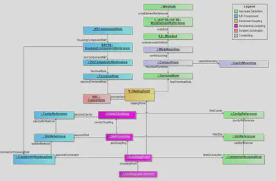
The electrical aspects of a coupling in concrete usage are defined with a MatingPoint and MatingDetails in the case terminals with multiple TerminalReceptions (see figure “Electrical Coupling” below).
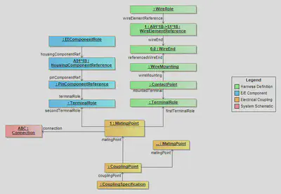
There are situations, where logical Connections are realized in physical layer directly by a pluggable “connection” (e.g. two E/E components are conntected directly to each other, see Direct Connectivity). Therefore, the MatingPoint can create traceability links into the schematic layer.
The CouplingPoint is used to group the information that is associated with a single coupling operation (e.g. all connections that are created with the plugging of a single connector). If this grouping is already known in the electrologic layer, it is useful (e.g. for traceability reasons) to group the MatingPoints in a CouplingPoint. However, if this is not know at the time of creation, it is perfectly valid to create an individual CouplingPoint for each mating. Nevertheless, when these ungrouped matings are assigned to a connector at a later stage, they shall be regrouped und a single CouplingPoint.
E/E Component Interface Definition
The assignment of electrical pins in an E/E-component to cavities of the mechanical interface is described in detail in the guideline about E/E-components.
Mechanical Compatibility and Mapping of Connectors
Coupling compatibility in the part master data is defined with a Mapping within a MappingSpecification. Due to the distributed nature of part master data the mapping is not defined with explicit reference, but by defining pairs of keys (e.g. CavityNumber). This is illustrated in the figure below. As you can see, the Mapping only requires links the PartVersions. Apart from that, it is self-contained and independant from the part master data definition. Therefore, it can be exchanged idenpendantly without then to embedd all ConnectorHousingSpecifications of the related connectors.
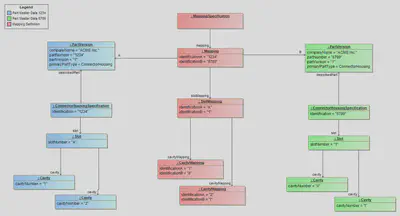
The semantic of the mapping is, that it describes a mapping for the ConnectorHousingSpecification “related” to the PartVersions, but what does “related” mean? Currently there are two PrimaryPartTypes that utilize the ConnectorHousingSpecification, ConnectorHousing and EEComponent.
For a ConnectorHousing “related” is defined as the ConnectorHousingSpecification that are referencing the PartVersion as describedPart. Usally this is just one. For an EEComponent “related” are the ConnectorHousingSpecifications that are used to by the HousingComponents of the EEComponent. This can be as many as there are HousingComponents. To resolve this ambiguity, the IdentificationA & IdentificationB relate to the Identification of the ConnectorHousingSpecification upon which the mapping is defined.
These properties (IdentificationA & IdentificationB in the Mapping) are optional for backwards compatibility, because they where first introduced in VEC 2.1. In versions before, there was chance to have an ambigious mapping for E/E components. See next section for an explanation.
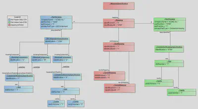
ConnectorHousingSpecifications in the Mapping, for data created with VEC 2.1 and later.Ambiguity of the Mapping (before V2.1)
The diagram below shows the situation for mappings before VEC V2.1. On the right side it is pretty clear, which slot is adressed SlotMapping.IdentificationB = 1, since the PartVersion 6789 is a “ConnectorHousing” and has only related ConnectorHousingSpecification. On the left hand side, this is only the case, because of the special situation illustrated in the diagram, where the ConnectorHousingSpecification “I” and “II” define different values for Slot.SlotNumber, which are unique within the scope of the E/E component.
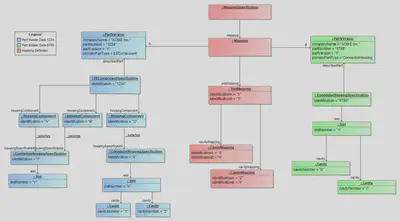
But, in general the SlotNumber is only required “to be unique within a ConnectorHousingSpecification”. So it would be perfectly valid for an E/E component to use ConnectorHousingSpecifications that define Slots with identical SlotNumbers like “A”, “1”, “default” or whatever else the specific naming convention of the process defines as appropriate. However, in this case it would not be possible to associate defined mapping with the correct ConnectorHousingSpecification.
Therefore, VEC V2.1 introduced corresponding “IdenticationA” & “IdenticationB” attributes in the Mapping (see diagram below). Despite having the same SlotNumbers un the right side, the mapping is defined unambigiously.
For backwards compatibility it is allowed to omit the Identification-attributes in the Mapping, but this is only permitted in cases where the mapping still can be associated unambigiously, even without the Identifications in the Mapping-class. This is normally the case for regular ConnectorHousing, which only a single related ConnectorHousingSpecification and EEComponents that satisfy the requirement of unique SlotNumbers within all ConnectorHousingSpecifications related to EECompionent (as illustrated in figure “Ambigious Mapping before VEC V2.1”).
To simplify the situation for future implementations, it is highly recommended to define the Identification-attributes in VEC V2.1 and later, even if they are not mandatory.
The only solution to define an unambigious mapping for situations like the one illustrated in figure “Unambigious Mapping for VEC V2.1 and later” in VEC versions before 2.1, is to define CustomPropertys for IdentificationA & B on the extendable Mapping-class.
Mechanical Coupling
As described in section Aspects of the Coupling the mechanical coupling in a specific usage can be derived from the part master data and the Mapping. The result of that process is stored in the “mechanical” part of the CouplingPoint. However, this derivation process is not necessarily required. As always, the VEC makes no assumption about the creation process of a specific information item, e.g. if the process requires a manual definition in the usage, this would be perfectly valid as well and the result of the process would stored in the CouplingSpecification.
It would also be imaginable to have a process where the definition of the coupling for a bordnet would happen after the development of all involved harnesses. In this case, the CouplingSpecification might be created in its own DocumentVersion.
The figure below contains an example of a completely defined CouplingPoint.