Harness (KBL/VEC Mapping)
Change History
| Id | Subject | Date |
|---|---|---|
| Latest Commit | Harness (KBL/VEC Mapping): instances of components and coupling (#1226) | 2026-11-13 |
| Restructured along the content of a harness description; overview of the mapping; KBL and VEC example files for download. | 2026-10-28 | |
| Parts and documents: PDM attributes, identity of the documents, multi-classified parts, title block information, external references. | 2026-10-28 | |
| Part master data: specifications per KBL part class, general technical information, connector housings, terminals, cavity seals and plugs. | 2026-10-28 | |
| Part master data of wires: single cores, multi-core wires, attributes and colour types. | 2026-10-28 | |
| Part master data of wire protections, fixings, accessories and co-pack parts. | 2026-10-28 | |
| Part master data of component boxes, fuses and other E/E components; section open topics. | 2026-10-28 | |
| Part master data of assembly parts. | 2026-10-28 | |
| Instances of components: roles per KBL occurrence, connectors, wires, wire protections, E/E components, instantiation of assemblies; coupling: mounting of fuses and components, mating of connectors; example file regenerated. | 2026-10-28 | |
| #1196 | One PartMaster document per component scoped to this mapping. | 2026-10-13 |
| #1178 | Layer rule moved to Composite Parts; COMPONENTS / MODULES as recommendation; variant specifications per harness description. | 2026-10-05 |
| #1174 | Instantiation of context relevant subcomponents; no SubComponent references for in-place modules. | 2026-10-02 |
| #1158 | Housekeeping: added missing content to the harness listing, aligned diagram labels, filled in classes. | 2026-09-28 |
| Started Implementation Guideline for Mapping a Harness in the VEC | 2025-02-13 |
Disclaimer: This page or section is currently under review by the community.
The content of this page or section can be subject to change at any time. If you find any issues or if you have any review comments please drop us an issue in our Issue Management on GitHub.
Editorial Note: Since the creation of this implementation guideline will span an extended period, the current work-in-progress versions will be published continuously to allow the community to review and provide feedback.
This implementation guideline outlines the core concepts needed to create a dataset for a single wiring harness in the VEC, which is also the use case that lies in the center of the scope of the KBL.
To ease adoption for those already familiar with the KBL, this guideline is structured as a mapping from the KBL model to the VEC model: it explains the VEC concepts together with the KBL concepts they correspond to and shows where the information of a KBL file is found in a VEC. Additionally, a reference implementation of a KBL-to-VEC converter is available on GitHub.
Disclaimer: This implementation guideline (along with the converter implementation) covers only the scope of the KBL. The VEC is a far more expressive model.
As a result, there are scenarios where the VEC could convey information with much clearer semantics. However, the necessary data for this level of precision is often not available in the KBL (e.g., detailed component data) or is embedded through custom properties and process/tool-specific dialects. “Healing” such data would require in-depth knowledge of the specific KBL dialect used and, in many cases, the integration of additional information sources (side-loading). This task lies outside the scope of this guideline. In situations where it is obvious that fixing of such deficiencies is advised, a Data Quality note is added.
The goal of this guideline is to demonstrate how standard KBL concepts map to VEC concepts—without improving the quality of the underlying information. While the VEC could indeed express many aspects more precisely, this guideline focuses on maintaining consistency with the original KBL data quality.
There are fundamentally two approaches to describing such a mapping. One can either start from the source model, explaining how its information is distributed into the target model, or take the opposite approach by defining which information is needed in the target model and where to find it in the source model. For this implementation guideline, the latter approach was chosen as the strategy.
On the one hand, the guideline’s focus is on how to describe a harness in the VEC, which naturally suggests describing the mapping from this perspective. On the other hand, the VEC is the more precise model, meaning that many KBL concepts are distributed across different elements within the VEC. For example, a KBL Node contains information relevant to the VEC concepts of a TopologyNode , GeometryNode2D and GeometryNode3D. It is more logical to describe the mapping of topology and 2D/3D geometry as cohesive units rather than addressing all three concepts in a mixed manner starting from the KBL Node.
The implementation guideline focuses on the structural mapping and covers individual attributes only where they are essential for understanding a concept. If you are interested in those details, please refer to the reference implementation. The guideline describes the concepts and not the converter: where the reference implementation currently deviates from this guideline or does not yet cover a concept, this is pointed out briefly.
The guideline follows a logical order rather than an order dictated by model dependencies. Since the VEC is a graph—not a strict tree—it allows cross-references between branches. As a result, you may encounter cases where a model element references another model element whose mapping is described later in this guideline.
A converter can address this challenge with a two-phase approach, as the reference implementation does: first all VEC elements are created, then the references between them are resolved.
The order of the sections follows the content of a harness description in the VEC (see Product Definition of a Harness):
- The Overview shows how the content of a KBL file is distributed across the VEC and introduces the principles that recur in all sections.
- Parts and Documents explains how KBL parts become
PartVersions andDocumentVersions. - Part Master Data describes the components used in the harness (connectors, terminals, wires, …).
- Harness Description describes the harness itself: the instances of the components, their coupling, the bill of material, the variants, the connectivity, and the topology with geometry, placement and routing.
- Basic Data Types covers the value types used everywhere (units, numerical values, strings, custom properties).
VEC XML snippets in this guideline are taken from the KBL to VEC conversion output of the reference implementation. Input for that is the sample KBL file Volkswagen - VOBES - Component Box. Both the KBL file and the resulting VEC file can be downloaded at the top of this page. The KBL file is the version used in the tests of the reference implementation. It differs from the published sample in two details: the node reference to the component box is corrected (in the published sample it references the Component_box_occurrence, which cannot be placed on a node), and a Housing_code is added to one connector housing.
Note the versions of the example files: the KBL file is a KBL 2.4 file, while the KBL class links in this guideline refer to KBL 2.5 (the classes used here are the same in both versions). The VEC file was created with the reference implementation as of November 2026 (harness-model develop) and declares VecVersion 2.2.0.
Topics that are not contained in this sample (e.g. wire protections, fixings, multi-core wires, module lists) are illustrated with other sample files of the reference implementation.
Overview
Everything starts with the model root element VecContent, see the figure below (all attributes omitted).
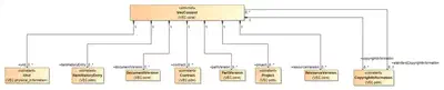
A KBL file (KBL_container) describes exactly one harness together with the parts used in it. In the VEC, this information is distributed as follows (the figure is conceptual and not precise syntax):

- Every KBL Part (including the Harness and its Modules) is identified by a
PartVersion. - The properties of the components (connectors, terminals, wires, …) are described in one
PartMasterdocument per component. - Everything that is specific to the harness—the instances of the components, their coupling, the bill of material, the variants, the connectivity, the topology, the geometry, the placements and the routings—is contained in a single
HarnessDescriptiondocument.
The following table shows where the KBL content is found in the VEC and in which section of this guideline the mapping is described.
Mapping Principles
The following principles recur throughout the mapping:
Part and usage. Like the KBL, the VEC distinguishes between the definition of a component type (KBL Part, e.g. Connector_housing) and its use in the harness (KBL Connection_or_occurrence, e.g. Connector_occurrence). In the VEC, the definition is made with PartOrUsageRelatedSpecifications in the PartMaster document of the component, the use with PartOccurrences and Roles in the harness description (see the guideline Component Instances). Since the KBL already follows this distinction, most concepts can be mapped in a straightforward manner.
One KBL element, several VEC elements. The VEC is more modular than the KBL. A KBL element often contains information that belongs to different views in the VEC. For example, a KBL Node contains information about the topology (TopologyNode), the geometry (GeometryNode2D or GeometryNode3D) and the placement of components (OnPointPlacement). Each view is described in its own section of this guideline.
Identification. VEC elements are identified by their Identification attribute, which must be unique within its context (see Identifiers). Where the KBL provides an Id, it is used. Where the VEC requires an identification that has no counterpart in the KBL (e.g. for the specifications of a part), the reference implementation derives one, e.g. from the abbreviated class name and the part number (CHS-ECP001706 for the ConnectorHousingSpecification of the part ECP001706). Such derived identifications are a convention of the reference implementation and not a VEC rule.
Parts and Documents
In the KBL, a Part combines the identification of a component (part number, version, company) with its technical description. The VEC separates both: the PartVersion identifies the part, the technical description is contained in the Specifications of a DocumentVersion (see General Structure – Parts and Documents). Each KBL part therefore results in a PartVersion and, for a component, in a PartMaster document.
PartVersions
The concept of parts is quite different in KBL and VEC. In the VEC a PartVersion is just a PDM-Header for the part. The various aspects of a part (e.g. is it a wire or connector) are handled by different types of PartOrUsageRelatedSpecifications contained in the DocumentVersion describing the part. In the KBL, the different types of parts are expressed as subclasses of Part. The concept in the VEC that most closely reflects the approach of the KBL is the PrimaryPartType.
PrimaryPartType is merely a preliminary “best guess” approach. In many cases, the “standard” KBL provides only a very general classification, whereas the VEC allows for more specific distinctions. For example, the KBL only recognizes Wire_protection, while the VEC differentiates between TubeSpecification, TapeSpecification, and others.The following PrimaryPartType could be used for KBL Parts:
| KBL Class | VEC PrimaryPartType |
|---|---|
| Accessory | Other |
| Co_pack_part | Other |
| Cavity_plug | CavityPlug |
| Cavity_seal | CavitySeal |
| General_wire | Wire |
| Connector_housing | ConnectorHousing |
| Fixing | Fixing |
| General_terminal | Terminal |
| Wire_protection | WireProtection |
| Harness | PartStructure |
| Harness_configuration | PartStructure |
| Module | PartStructure |
| Assembly_part | PartStructure |
| Fuse | Fuse |
| Component_box | EEComponent |
| Component | EEComponent |
When mapping into the VEC, a PartVersion Object is required for each KBL Part. Those can be found under /KBL_container/(Accessory|AssemblyPart|CavityPlug|...), /KBL_container/Harness/Module and /KBL_container/Harness/Harness_configuration.
The PDM attributes of the Part are mapped directly to the PartVersion: Part_number, Company_name and Version become PartNumber, CompanyName and PartVersion, which together identify the part in the VEC. Abbreviation and Description (and Localized_description) become localized strings (see Strings and Localized Strings). Each Alias_identification becomes an AliasIdentification, where the KBL Description (“the type of the Alias_identification”) is mapped to the Type. The Part_number_type corresponds to the PartNumberType of the PartVersion.
<!-- KBL -->
    <Connector_housing id="id_315_0">
        <Part_number>ECP001706</Part_number>
        <Company_name>MaybeAnyCompany</Company_name>
        <Alias_id id="id_368_27">
            <Alias_id>TBL001038B</Alias_id>
            <Scope>VOBES</Scope>
            <Description>tab_number</Description>
        </Alias_id>
        <Version>1</Version>
        <Abbreviation>/NULL</Abbreviation>
        <Description>BUCHSENGEHAEUSE_6-POL</Description>
        ...
    </Connector_housing>
<!-- VEC -->
  <PartVersion id="PartVersion_id_315_0">
    ...
    <Description xsi:type="vec:LocalizedString" id="LocalizedString_00195">
      <LanguageCode>De</LanguageCode>
      <Value>BUCHSENGEHAEUSE_6-POL</Value>
    </Description>
    <CompanyName>MaybeAnyCompany</CompanyName>
    <PartNumber>ECP001706</PartNumber>
    <PartVersion>1</PartVersion>
    <PrimaryPartType>ConnectorHousing</PrimaryPartType>
    <AliasId id="AliasIdentification_id_368_27">
      <IdentificationValue>TBL001038B</IdentificationValue>
      <Type>tab_number</Type>
      <Scope>VOBES</Scope>
    </AliasId>
  </PartVersion>
Data Quality: The KBL allows to have the same Part_number under different classifications (see Part for more details). In the VEC, multiple occurrences of the same part version are considered a semantic error. In KBL data, there are two different reasons for such duplicates, which have to be treated differently:
- The same part is used in different roles. For example, a tape can be used as Wire_protection or as Accessory to some other part, or a cable tie as Accessory and as Fixing. Due to other modeling approaches in the VEC, there is no longer any need for this. The duplicates are merged into a single
PartVersionwhosePartMasterdocument contains all specifications that are required for the different aspects of the part (see Hybrid and Composite Components). The occurrences are not affected: each of them references the mergedPartVersionand has the role that corresponds to its usage. - A workaround for terminals without a connector housing. Typical examples are the cable lugs in VOBES data, which are defined both as Connector_housing and as General_terminal with the same part number (e.g.
ECP001135in the example file). Here, the Connector_housing does not describe a real component: it is a “virtual” housing that is only needed because the KBL can attach wires to a terminal only via a contact point in a connector occurrence. Such parts must not be merged into onePartVersionwith aConnectorHousingSpecificationand aTerminalSpecification. Instead, the virtual housing should be resolved, which also changes the occurrences and the contacting. This is explained in detail in Connector Housings – Virtual Connector Housings.
Both cases should be cleaned up in a pre- or post-processing of the conversion. Since both result in the same part number under different classifications, distinguishing them requires knowledge of the KBL dialect. The reference implementation is free of dialect knowledge and keeps the duplicates.
DocumentVersions
Disclaimer: This page or section is currently under review by the community.
The content of this page or section can be subject to change at any time. If you find any issues or if you have any review comments please drop us an issue in our Issue Management on GitHub.
This page or section resolves #1196
In the VEC, all payload data is contained within DocumentVersions. Typically, you would structure those according to the actual documents used in the process. Unfortunately, this concept in its detail form is not present in the KBL. Therefore, for the generic conversion described here, practical assumptions need to be made:
- It is common practice to describe components in individual datasets/documents and publish them separately → one
DocumentVersionfor each harness component (e.g. connector, wire and terminal, see Partitioning and Sizing), see section Part Master Data. - It is also common for a wiring harness to be fully described in a single 150% dataset, containing all information about the used component occurrences, variants, connectivity, dimensioning, and so on → one
DocumentVersionfor the harness itself, see section Harness Description.
This means that, for this mapping, a DocumentVersion with DocumentType=PartMaster must be created for each component used in the wiring harness. These are all instances of Part in the KBL except instances of Part_with_title_block.
For the Harness itself, a DocumentVersion with DocumentType=HarnessDescription is created. This document contains all relevant information about the harness as well as the Specifications for the Modules and Harness_configurations.
Identity of the Documents
Since the KBL has no explicit document concept, the identity of the documents must be derived. The natural choice is the identity of the described part: DocumentNumber, DocumentVersion and CompanyName of the document are taken from Part_number, Version and Company_name of the part, and the document references the part as ReferencedPart. If the identities of the actual documents in the process are known, they should be used instead.
  <DocumentVersion id="DocumentVersion_id_315_0">
    ...
    <CompanyName>MaybeAnyCompany</CompanyName>
    <DocumentNumber>ECP001706</DocumentNumber>
    <DocumentType>PartMaster</DocumentType>
    <DocumentVersion>1</DocumentVersion>
    <ReferencedPart>PartVersion_id_315_0</ReferencedPart>
    <RelatedDocument>DocumentVersion_External_reference_1</RelatedDocument>
    <Specification xsi:type="vec:ConnectorHousingSpecification" id="ConnectorHousingSpecification_id_315_0">
      <Identification>CHS-ECP001706</Identification>
      ...
The same applies to the HarnessDescription, whose identity is derived from the Harness. A harness description defines not only the harness, but also its modules and harness configurations. All PartVersions defined in the document should therefore be referenced as ReferencedPart (see Product Definition of a Harness). The reference implementation currently references only the PartVersion of the harness.
  <DocumentVersion id="DocumentVersion_id_328_0_1">
    ...
    <CompanyName>MaybeAnyCompany</CompanyName>
    ...
    <DocumentNumber>LTG0011200</DocumentNumber>
    <DocumentType>HarnessDescription</DocumentType>
    <DocumentVersion>2.4.0</DocumentVersion>
    <ReferencedPart>PartVersion_id_328_0</ReferencedPart>
    <RelatedDocument>DocumentVersion_External_reference_12 DocumentVersion_id_322_0 DocumentVersion_id_322_1</RelatedDocument>
    ...
Title Block and PDM Information
The KBL distributes the information of a drawing title block over several places: Creation, Approval and Change_description are defined directly in the KBL_container and reference the parts they apply to (Is_applied_to); a Part can have Changes and a Copyright_note; and the Part_with_title_block (i.e. the Harness, Module and Harness_configuration) adds project and car classification information. In the VEC, this is meta information of the DocumentVersion that contains the definition (see PDM Information), and in some cases of the PartVersion.
| KBL | VEC |
|---|---|
Creation (Name, Department, Date) | Creation of the DocumentVersion |
Approval (Name, Department, Date, Type_of_approval) | Approval of the DocumentVersion |
Change (Change) and Change_description | ChangeDescription of the DocumentVersion |
Copyright_note | CopyrightInformation in the VecContent, referenced by the DocumentVersion / PartVersion |
Project_number, Car_classification_level_2 to _4 | Project in the VecContent, referenced by the PartVersion |
The target DocumentVersion of a Creation, Approval or Change_description is the document that describes the part referenced by Is_applied_to. The structures are not identical: in the VEC, persons are described by a Person, and some attributes are mandatory that have no KBL source (e.g. the Status of an Approval), so they have to be filled with a default value (see Default Values).
The title block information of the KBL Harness belongs to the HarnessDescription. The title block information of a Module or Harness_configuration does not have a document of its own in the VEC, since modules and configurations are defined within the HarnessDescription. Where it differs from the harness, it can only be preserved on the PartVersion (e.g. Project, CopyrightInformation).
The following excerpt shows the copyright note and the change of the harness in the example file. The CopyrightInformation is defined once in the VecContent and referenced by the HarnessDescription and by the PartVersion of the harness; the change becomes a ChangeDescription of the HarnessDescription.
<!-- KBL -->
    <Harness id="id_328_0">
        ...
        <Copyright_note>Copyright reserved: Volkswagen AG behält sich alle Rechte vor. ...
        ...
        <Change id="Change_1">
            <Description>KBL 2.4 Sample File</Description>
            <Change_date>270115</Change_date>
            <Responsible_designer>Kyriazis</Responsible_designer>
            <Designer_department>K-SIPE-3</Designer_department>
        </Change>
        ...
<!-- VEC -->
  <CopyrightInformation id="CopyrightInformation_id_328_0">
    <CopyrightNote id="LocalizedString_00000">
      <LanguageCode>De</LanguageCode>
      <Value>Copyright reserved: Volkswagen AG behält sich alle Rechte vor. ...
      ...
    </CopyrightNote>
  </CopyrightInformation>
  ...
  <DocumentVersion id="DocumentVersion_id_328_0_1">
    ...
    <CopyrightInformation>CopyrightInformation_id_328_0</CopyrightInformation>
    <ChangeDescription id="ChangeDescription_Change_1">
      <Description xsi:type="vec:LocalizedString" id="LocalizedString_00180">
        <LanguageCode>De</LanguageCode>
        <Value>KBL 2.4 Sample File</Value>
      </Description>
      <ChangeDate>2015-01-27T00:00:00</ChangeDate>
      <ResponsibleDesigner id="Person_00181">
        <Department>K-SIPE-3</Department>
        <LastName>Kyriazis</LastName>
      </ResponsibleDesigner>
    </ChangeDescription>
    ...
Data Quality: The dates in the KBL are strings without a defined format (e.g. 270115 in the example file), whereas the VEC uses xs:date / xs:dateTime. A conversion requires knowledge of the date format used in the KBL dialect.
The reference implementation converts Changes, Creations and Approvals into the DocumentVersion that contains the definition of the part (into the PartVersion for a Module, which has no document of its own), and the Copyright_note into a CopyrightInformation. The date formats of the KBL are a parameter of the conversion (by default dd.MM.yyyy and ddMMyy). The project and car classification information is not converted yet.
External References
A KBL External_reference identifies a document that is not part of the KBL file (e.g. a 3D model or a drawing). Its counterpart in the VEC is a DocumentVersion that contains only PDM information and no specifications (see Usages of the DocumentVersion). Document_number, Change_level, Data_format, Creating_system and Location are mapped to the attributes of the same meaning. The KBL Document_type literals (part master, geometry model, harness description, …) have direct counterparts in the VEC DocumentType (PartMaster, GeometryModel, HarnessDescription, …). Values outside the KBL enumeration are kept as they are.
<!-- KBL -->
    <External_reference id="External_reference_1">
        <Document_type>EKR</Document_type>
        <Document_number>ECP001706</Document_number>
        <Change_level>011112</Change_level>
        <File_name>ECP001706.CATPart</File_name>
        <Data_format>catPart</Data_format>
        <Creating_system>CATIA V5R19 SP9</Creating_system>
    </External_reference>
<!-- VEC -->
  <DocumentVersion id="DocumentVersion_External_reference_1">
    <CompanyName>ACME Inc.</CompanyName>
    <DocumentNumber>ECP001706</DocumentNumber>
    <DocumentType>EKR</DocumentType>
    <DocumentVersion>011112</DocumentVersion>
    <CreatingSystem>CATIA V5R19 SP9</CreatingSystem>
    <DataFormat>catPart</DataFormat>
    <FileName>ECP001706.CATPart</FileName>
  </DocumentVersion>
Two details need attention:
- The
CompanyNameis mandatory in the VEC, but the KBL External_reference has no company. If the company is not known from the context,/NULLshould be used (see Default Values). The valueACME Inc.in the example is a placeholder of the reference implementation. - The
FileNameof a VECDocumentVersionis reserved for documents that are part of the VEC package; otherwise it shall be omitted (see External References). The KBLFile_namerefers to a file outside of the KBL, so it should only be kept if the document is packaged together with the VEC file. The document can still be resolved via its domain key or via theLocation, if given in the KBL.
The KBL External_references of a Part are the documents associated with the part (e.g. its 3D model). In the VEC, this relation can be expressed with different associations; the one with the most specific semantics should be chosen (see External References). For documents describing the part, this is ReferencedPart of the referenced DocumentVersion. The reference implementation uses the more general RelatedDocument of the PartMaster document (see the example above).
Part Master Data
For all components used in a wiring harness, a minimum set of part master data is required.
A PartMaster document contains all PartOrUsageRelatedSpecifications that are required to describe the component. For a general description of this concept see the Guideline “Component Description”. The specifications that have to be created are listed below. The mapping of those is described in the following sections.
The following table defines the PartOrUsageRelatedSpecification that are used to define each Part. Auxiliary specifications that might be required by the PartOrUsageRelatedSpecification for a complete definition (e.g. WireReceptionSpecification, CavitySpecification or InsulationSpecification) are listed in the corresponding section.
In addition, every part receives a GeneralTechnicalPartSpecification (see General Technical Information). The Harness, its Modules and Harness_configurations do not have a PartMaster document. They are defined in the HarnessDescription (see Bill of Material / Part Structure).
The PlaceableElementSpecification is required for all components that are placed on the topology (see Placement). In the KBL, these are the components whose occurrences can be referenced by a Node (Referenced_components), by a Fixing_assignment or by a Protection_area.
General Technical Information
In this mapping, every part receives a GeneralTechnicalPartSpecification (this is a convention, the VEC does not require it); that is, for each instance of a KBL Part, such a specification is created in its describing DocumentVersion. This specification covers basic technical information about the component, such as dimensions, weight, material, and dependencies to other parts.
| KBL | VEC GeneralTechnicalPartSpecification |
|---|---|
Mass_information (Part) | MassInformation |
Material_information (Part) | MaterialInformation |
Housing_colour (Connector_housing), Colour (Cavity_seal, Cavity_plug, Fuse) | ColorInformation |
The XML representation for the multi-fuse of the example file looks as follows:
<!-- KBL -->
    <Assembly_part id="id_304_1">
        <Part_number>AS0105563</Part_number>
        ...
        <Mass_information id="id_380_1">
            <Unit_component>id_346_2</Unit_component>
            <Value_component>47.7</Value_component>
        </Mass_information>
        ...
<!-- VEC -->
    <Specification xsi:type="vec:GeneralTechnicalPartSpecification" id="GeneralTechnicalPartSpecification_id_304_1">
      <Identification>GTPS-AS0105563</Identification>
      <DescribedPart>PartVersion_id_304_1</DescribedPart>
      <MassInformation id="MassInformation_id_380_1">
        <Value id="NumericalValue_id_380_1">
          <UnitComponent>SIUnit_id_346_2</UnitComponent>
          <ValueComponent>47.7</ValueComponent>
        </Value>
      </MassInformation>
    </Specification>
In the KBL, colours and materials are plain strings. In the VEC, a Color and a Material consist of a key and the reference system that defines the meaning of the key (e.g. RAL for colours). The reference system is not contained in the KBL and must be known from the context of the KBL dialect (e.g. a company specific colour code).
ACME Inc. as reference system. It also attaches the KBL Processing_information of a part as CustomProperty to the PartVersion. Since a PartVersion should contain only PDM information, the GeneralTechnicalPartSpecification is the better place for them (see Custom Properties and Instructions).Connector Housings
A KBL Connector_housing has the same basic structure as a VEC ConnectorHousingSpecification: the housing consists of Slots, which consist of Cavitys. Both are mapped 1:1 to a Slot and a Cavity, where the Id of the KBL slot becomes the SlotNumber and the Cavity_number becomes the CavityNumber. The Housing_code is mapped to the Coding and the Housing_type to the SpecialPartType of the ConnectorHousingSpecification. The Number_of_cavities of a KBL slot can be represented by a SlotSpecification.
Since connectors are placed on the topology, a PlaceableElementSpecification with ValidPlacementTypes=OnPoint is added to the PartMaster document.
<!-- KBL -->
    <Connector_housing id="id_315_0">
        <Part_number>ECP001706</Part_number>
        ...
        <Housing_colour>schwarz</Housing_colour>
        <Housing_code>A</Housing_code>
        <Slots id="id_341_0">
            <Id>default</Id>
            <Number_of_cavities>6</Number_of_cavities>
            <Cavities id="id_370_0">
                <Cavity_number>1</Cavity_number>
            </Cavities>
            ...
        </Slots>
    </Connector_housing>
<!-- VEC -->
    <Specification xsi:type="vec:ConnectorHousingSpecification" id="ConnectorHousingSpecification_id_315_0">
      <Identification>CHS-ECP001706</Identification>
      <DescribedPart>PartVersion_id_315_0</DescribedPart>
      <Coding id="Coding_00021">
        <Coding>A</Coding>
      </Coding>
      <Slot xsi:type="vec:Slot" id="Slot_id_341_0">
        <SlotNumber>default</SlotNumber>
        <Cavity id="Cavity_id_370_0">
          <CavityNumber>1</CavityNumber>
        </Cavity>
        ...
      </Slot>
    </Specification>
    <Specification xsi:type="vec:PlaceableElementSpecification" id="PlaceableElementSpecification_id_315_0">
      <Identification>PES-ECP001706</Identification>
      <DescribedPart>PartVersion_id_315_0</DescribedPart>
      <ValidPlacementTypes>OnPoint</ValidPlacementTypes>
    </Specification>
    <Specification xsi:type="vec:GeneralTechnicalPartSpecification" id="GeneralTechnicalPartSpecification_id_315_0">
      <Identification>GTPS-ECP001706</Identification>
      <DescribedPart>PartVersion_id_315_0</DescribedPart>
      <ColorInformation id="Color_00022">
        <Key>schwarz</Key>
        <ReferenceSystem>ACME Inc.</ReferenceSystem>
      </ColorInformation>
    </Specification>
Virtual Connector Housings
Not every Connector_housing in a KBL file describes a real connector. Many KBL files contain “virtual” connector housings, which are a workaround for a gap in the KBL model.
Background. The KBL attaches a wire to a terminal via a Contact_point: the Extremity of the Connection references the contact point, and the contact point references the terminal (Associated_parts) and the cavity (Contacted_cavity). Contact points, however, can only be defined in a Connector_occurrence (or a Component_box_occurrence). The Special_terminal_occurrence was introduced to describe terminals that are not inserted into a connector housing, e.g. ring terminals or cable lugs, but it cannot contain contact points. A wire therefore cannot be attached to it directly. As a workaround, a connector housing is defined whose only purpose is to provide a home for the contact point. The same workaround is used for splices and for wire ends without a connector (“danglers”).
Dialects. The workaround has been implemented differently by the individual KBL dialects, for example:
- The virtual Connector_housing has the part number of the terminal (as for the cable lugs in VOBES data) or a dummy part number.
- The virtual Connector_occurrence is marked with a
Usage(ring terminal,splice,dangler,no end) or not at all. - The terminal is instantiated as a Special_terminal_occurrence, as a Terminal_occurrence, or not at all (e.g. for splices without material).
- The virtual housing has slots and cavities (sometimes with the slot
Idnone), which are referenced asContacted_cavity. - The node that places the element references the virtual connector occurrence or the terminal occurrence.
The example file contains such a case for the battery terminal XA.A.1. The part ECP001135 is defined both as Connector_housing (with one slot none and one cavity) and as General_terminal (cable_shoe). In the harness, XA.A.1 is instantiated twice: as a Connector_occurrence with Usage=ring terminal, which contains the contact point, and as a Special_terminal_occurrence, which is associated with the contact point and placed on the node.
<!-- KBL -->
    <Connector_housing id="id_315_9">
        <Part_number>ECP001135</Part_number>
        ...
        <Description>BATTERIEKLEMME_PLUS</Description>
        ...
        <Slots id="id_341_21">
            <Id>none</Id>
            <Number_of_cavities>1</Number_of_cavities>
            <Cavities id="id_370_62">
                <Cavity_number>1</Cavity_number>
            </Cavities>
        </Slots>
    </Connector_housing>
    ...
    <General_terminal id="id_326_11">
        <Part_number>ECP001135</Part_number>
        ...
        <Description>cable_shoe</Description>
        <Terminal_type>special</Terminal_type>
        <Plating_material>sn</Plating_material>
    </General_terminal>
    ...
        <Connector_occurrence id="id_316_12">
            <Id>XA.A.1</Id>
            <Usage>ring terminal</Usage>
            <Part>id_315_9</Part>
            <Contact_points id="id_372_4">
                <Id>XA.A.1-1#100_4_XA.SR1.1_1_1</Id>
                <Associated_parts>id_342_4</Associated_parts>
                <Contacted_cavity>id_370_63</Contacted_cavity>
            </Contact_points>
            ...
            <Slots id="id_341_22">
                <Part>id_341_21</Part>
                <Cavities id="id_370_63">
                    <Part>id_370_62</Part>
                </Cavities>
            </Slots>
        </Connector_occurrence>
        ...
        <Special_terminal_occurrence id="id_342_4">
            <Id>XA.A.1</Id>
            ...
            <Part>id_326_11</Part>
            ...
    <Node id="Node_15">
        ...
        <Referenced_components>id_342_4</Referenced_components>
    </Node>
Detection. Whether a connector housing is virtual cannot be decided from the KBL model alone, because the workaround uses regular KBL elements. Indications can be the Usage of the occurrence, a part number that is also used for a terminal, a dummy part number or a slot none. Which of them are reliable, and how the information of the involved elements has to be combined, depends entirely on the KBL dialect and requires knowledge about it.
Target representation in the VEC. The VEC does not have this gap: a ContactPoint is not contained in a connector, and it can reference a terminal without a cavity. A VEC should therefore not reproduce the workaround. The terminal is represented by a terminal occurrence of its own, and the contacting by a ContactPoint without CavityMounting (see Wiring – Ringterminal - Splice).
Example strategy. The following figure and table show a possible strategy to resolve the workaround for the example above. It is derived from example files of a single dialect (VOBES) and is not a general mapping rule; other dialects require other strategies.

| KBL (VOBES example) | VEC (possible strategy) |
|---|---|
| virtual Connector_housing | no ConnectorHousingSpecification. If it has the part number of the terminal, its PartVersion is the one of the terminal, with a terminal specification only. A dummy part has no PartVersion at all. |
| General_terminal | PartVersion with the specification of the terminal type (RingTerminalSpecification, SpliceTerminalSpecification, …) and a PlaceableElementSpecification |
| virtual Connector_occurrence and the terminal occurrence | one PartOccurrence of the terminal with the corresponding role (e.g. RingTerminalRole) and a PlaceableElementRole. Identification, alias ids, descriptions and installation information of both KBL occurrences are combined. The slot and cavity occurrences of the virtual housing are not mapped. |
| Contact_point | ContactPoint with the terminal role as MountedTerminal and a WireMounting for the wire ends, but without CavityMounting (see Wiring – Ringterminal - Splice) |
Referenced_components of the Node (virtual connector occurrence or terminal occurrence) | OnPointPlacement of the PlaceableElementRole of the terminal occurrence |
For the other kinds of virtual connectors, the target representation in the VEC is:
- Splices (
Usage=splice): the splice is a terminal with aSpliceTerminalSpecificationand aSpliceTerminalRole. If the KBL contains no terminal for the splice (e.g. for ultrasonic welding), the specification describes the process instead of a real component (see Splices). - Wire ends without a connector (
Usage=danglerorno end): there is no component at the wire end. If the location of the open wire end is relevant, it can be described with anOpenWireEndTerminalSpecificationand anOpenWireEndTerminalRole.
PartVersions with the same identity. Resolving the workaround is the task of a dialect-specific pre- or post-processing.Terminals
A KBL General_terminal is described with a few flat attributes. The VEC TerminalSpecification describes the inner structure of a terminal: a WireReception for the connection of the wire, a TerminalReception for the connection to the mating terminal, and an InternalTerminalConnection between them. The properties of the receptions are defined by a WireReceptionSpecification and a TerminalReceptionSpecification, which are auxiliary specifications in the same PartMaster document.
For a terminal from the KBL, this structure consists of exactly one wire reception, one terminal reception and the connection between them. The attributes of the KBL terminal are distributed as follows:
| KBL General_terminal | VEC |
|---|---|
Terminal_type | SpecialPartType of the TerminalSpecification. Special terminal types have their own specification classes, e.g. RingTerminalSpecification or SpliceTerminalSpecification; selecting them requires knowledge of the KBL dialect (see below). |
Plating_material | PlatingMaterial of the TerminalReceptionSpecification (and of the WireReceptionSpecification, if it applies to the whole terminal) |
Cross_section_area | CoreCrossSectionArea of the WireReceptionSpecification |
Outside_diameter | WireElementOutsideDiameter of the WireReceptionSpecification |
<!-- KBL -->
    <General_terminal id="id_326_0">
        <Part_number>TER00156401</Part_number>
        ...
        <Plating_material>au</Plating_material>
    </General_terminal>
<!-- VEC -->
    <Specification xsi:type="vec:TerminalSpecification" id="TerminalSpecification_id_326_0">
      <Identification>TS-TER00156401</Identification>
      <DescribedPart>PartVersion_id_326_0</DescribedPart>
      <InternalTerminalConnection id="InternalTerminalConnection_id_326_0">
        <Identification>ITC</Identification>
        <TerminalReception>TerminalReception_id_326_0</TerminalReception>
        <WireReception>WireReception_id_326_0</WireReception>
      </InternalTerminalConnection>
      <TerminalReception id="TerminalReception_id_326_0">
        <Identification>TR</Identification>
        <TerminalReceptionSpecification>TerminalReceptionSpecification_id_326_0</TerminalReceptionSpecification>
      </TerminalReception>
      <WireReception id="WireReception_id_326_0">
        <Identification>WR</Identification>
        <WireReceptionSpecification>WireReceptionSpecification_id_326_0</WireReceptionSpecification>
      </WireReception>
    </Specification>
    <Specification xsi:type="vec:WireReceptionSpecification" id="WireReceptionSpecification_id_326_0">
      <Identification>WRS</Identification>
    </Specification>
    <Specification xsi:type="vec:TerminalReceptionSpecification" id="TerminalReceptionSpecification_id_326_0">
      <Identification>TRS</Identification>
      <PlatingMaterial id="Material_00035">
        <Key>au</Key>
        <ReferenceSystem>ACME Inc.</ReferenceSystem>
      </PlatingMaterial>
    </Specification>
Terminals that are used on their own and placed on the topology (KBL Special_terminal_occurrence, e.g. a ring terminal at a ground bolt) additionally require a PlaceableElementSpecification.
The structure with one wire reception and one terminal reception does not fit all terminal types. An end splice, for example, has only a wire reception (see Splices). If the Terminal_type indicates such a terminal, the structure should be adapted accordingly.
However, the Terminal_type is an open enumeration in the KBL. Besides the predefined values (e.g. ring terminal, splice, open wire end), the dialects use values of their own; the cable lugs in the example file, for instance, have the type special. Recognizing the kind of a terminal from its Terminal_type, and thus adapting the structure and selecting a more specific specification class, therefore requires knowledge of the KBL dialect. The reference implementation is free of dialect knowledge: it keeps the Terminal_type as SpecialPartType and creates the same structure for all terminals.
Cavity Seals and Cavity Plugs
Cavity seals and cavity plugs are mapped to a CavitySealSpecification and a CavityPlugSpecification.
| KBL | VEC |
|---|---|
Cavity_seal.Seal_type | SpecialPartType of the CavitySealSpecification |
Cavity_seal.Wire_size | WireElementOutsideDiameter of the CavitySealSpecification |
Cavity_plug.Plug_type | SpecialPartType of the CavityPlugSpecification |
Colour | ColorInformation of the GeneralTechnicalPartSpecification |
The cavity in which a seal or plug is used and the wire that is sealed are not part of the part master data. They are described by the Connectivity of the harness.
Wires
A KBL General_wire describes a wire with flat attributes. If it is a multi-core wire, it contains a list of Cores with similar attributes. The VEC describes a wire as a tree of WireElements in a WireSpecification. Each WireElement references a WireElementSpecification, which defines its properties with a ConductorSpecification (here: CoreSpecification) and an InsulationSpecification. The background of this structure is explained in the guideline Wires.
The instances of a wire in the harness do not reference the specifications, but the WireElements (see Instances of Components). This is why a WireElement is required for every wire and every core, although it has no direct counterpart in the KBL.
Single cores. A General_wire without Cores is a single core. For single cores, the minimal representation shall be used (see Wires – Definition of a Single Core): one WireElement with one WireElementSpecification that references both the CoreSpecification and the InsulationSpecification.
<!-- KBL -->
    <General_wire id="id_327_1">
        <Part_number>WIR0010006</Part_number>
        ...
        <Wire_type>individual wire</Wire_type>
        <Bend_radius id="id_369_1">
            <Unit_component>id_346_1</Unit_component>
            <Value_component>4</Value_component>
        </Bend_radius>
        <Cross_section_area id="id_375_1">
            <Unit_component>id_346_0</Unit_component>
            <Value_component>0.5</Value_component>
        </Cross_section_area>
        <Outside_diameter id="id_381_1">
            <Unit_component>id_346_1</Unit_component>
            <Value_component>1</Value_component>
        </Outside_diameter>
        <Cover_colour id="id_374_1">
            <Colour_type>Grundfarbe</Colour_type>
            <Colour_value>ws</Colour_value>
        </Cover_colour>
        <Cover_colour id="id_374_2">
            <Colour_type>Kennfarbe</Colour_type>
            <Colour_value>gn</Colour_value>
        </Cover_colour>
    </General_wire>
<!-- VEC -->
    <Specification xsi:type="vec:WireSpecification" id="WireSpecification_id_327_1">
      <Identification>WS-WIR0010006</Identification>
      <DescribedPart>PartVersion_id_327_1</DescribedPart>
      <WireElement id="WireElement_id_327_1">
        <Identification>WIRE</Identification>
        <WireElementSpecification>WireElementSpecification_id_327_1</WireElementSpecification>
      </WireElement>
    </Specification>
    ...
    <Specification xsi:type="vec:WireElementSpecification" id="WireElementSpecification_id_327_1">
      <Identification>WIRE</Identification>
      <Type id="WireType_00062">
        <Type>individual wire</Type>
        <ReferenceSystem>ACME Inc.</ReferenceSystem>
      </Type>
      <MinBendRadiusStatic id="NumericalValue_id_369_1">
        ...
      </MinBendRadiusStatic>
      <OutsideDiameter id="NumericalValue_id_381_1">
        ...
      </OutsideDiameter>
      <ConductorSpecification>CoreSpecification_id_327_1</ConductorSpecification>
      <InsulationSpecification>InsulationSpecification_id_327_1</InsulationSpecification>
    </Specification>
    <Specification xsi:type="vec:InsulationSpecification" id="InsulationSpecification_id_327_1">
      <Identification>WIRE-INS</Identification>
      ...
      <BaseColor id="Color_00063">
        <Key>ws</Key>
        <ReferenceSystem>ACME Inc.</ReferenceSystem>
      </BaseColor>
      <FirstIdentificationColor id="Color_00064">
        <Key>gn</Key>
        <ReferenceSystem>ACME Inc.</ReferenceSystem>
      </FirstIdentificationColor>
    </Specification>
    ...
    <Specification xsi:type="vec:CoreSpecification" id="CoreSpecification_id_327_1">
      <Identification>WIRE-CORE</Identification>
      <CrossSectionArea id="NumericalValue_id_375_1">
        <UnitComponent>SIUnit_id_346_0</UnitComponent>
        <ValueComponent>0.5</ValueComponent>
      </CrossSectionArea>
    </Specification>
Multi-core wires. A General_wire with Cores becomes a WireElement for the whole cable with one sub wire element per core. The WireElementSpecification of the cable carries the properties of the cable (e.g. outside diameter, bend radius) and the InsulationSpecification of the jacket, but no conductor. Each core has its own WireElementSpecification with a CoreSpecification and an InsulationSpecification.

The Id of the core is used as identification of its WireElement. The following excerpt shows the structure for a two-core cable of the KSK sample of the reference implementation:
    <Specification xsi:type="vec:WireSpecification" id="WireSpecification_id_327_89">
      <Identification>WS-O10a71692144</Identification>
      ...
      <WireElement id="WireElement_id_327_89">
        <Identification>WIRE</Identification>
        <WireElementSpecification>WireElementSpecification_id_327_89</WireElementSpecification>
        <SubWireElement id="WireElement_id_317_0">
          <Identification>2-ws@N_906_581_33</Identification>
          <WireElementSpecification>WireElementSpecification_id_317_0</WireElementSpecification>
        </SubWireElement>
        <SubWireElement id="WireElement_id_317_1">
          <Identification>1-ws@N_906_581_33</Identification>
          <WireElementSpecification>WireElementSpecification_id_317_1</WireElementSpecification>
        </SubWireElement>
      </WireElement>
    </Specification>
The KBL cannot express further inner structures of a multi-core wire, like twisting, shields or fillers. If such information is encoded in a KBL dialect (e.g. a Wire_type=twist for twisted cores), it should be mapped to the corresponding VEC concepts (e.g. a WireGroupSpecification, see Wires – Definition of a Multicore Wire).
Attributes. The attributes of a General_wire and a Core are mapped as follows:
| KBL General_wire / Core | VEC |
|---|---|
Wire_type | Type of the WireElementSpecification |
Outside_diameter | OutsideDiameter of the WireElementSpecification |
Bend_radius | MinBendRadiusStatic of the WireElementSpecification |
Cross_section_area | CrossSectionArea of the CoreSpecification (single cores and cores only) |
Cover_colour / Core_colour | colours of the InsulationSpecification, see below |
The colours of a wire are typed in both models. The KBL Colour_type literals have a direct counterpart in the InsulationSpecification:
KBL Colour_type | VEC InsulationSpecification |
|---|---|
base colour | BaseColor |
first identification | FirstIdentificationColor |
second identification | SecondIdentificationColor |
label identification | LabelIdentificationColor |
Colour_type is an open enumeration in the KBL, and some dialects use their own values (e.g. Grundfarbe and Kennfarbe in the example above). These values must be mapped to the VEC attributes with knowledge of the dialect. The reference implementation currently ignores the Colour_type and assigns the colours in the order of the KBL file (first colour as base colour, second colour as first identification colour, …), which is only correct if the KBL file follows this order. As for all colours, the reference system is not contained in the KBL (see General Technical Information).Wire Protections, Fixings and Accessories
These components have in common that the KBL provides only a classification string and little or no technical data for them. In the VEC, they are described with the specification that matches the classification as closely as possible; the KBL classification string is kept as SpecialPartType.
Wire protections. A Wire_protection becomes a WireProtectionSpecification with the Protection_type as SpecialPartType. The VEC distinguishes different kinds of wire protections with more specific subclasses (TapeSpecification, TubeSpecification, CorrugatedPipeSpecification, …). If the Protection_type of a KBL dialect allows to identify the kind (e.g. TAPE), the more specific class should be used. This is especially relevant for tapes, since the processing information of a tape (winding type, taping direction, …) can only be expressed with the TapeRole of a TapeSpecification (see Tapes and Tubes). Since wire protections are placed along the topology, the PlaceableElementSpecification allows the placement type OnWay.
The following example is taken from the generator cable sample of the reference implementation, which does not yet use the more specific classes:
<!-- KBL -->
    <Wire_protection id="Wire_protection_1">
        <Part_number>O1112a614541a2</Part_number>
        ...
        <Protection_type>TAPE</Protection_type>
    </Wire_protection>
<!-- VEC -->
    <Specification xsi:type="vec:WireProtectionSpecification" id="WireProtectionSpecification_Wire_protection_1">
      <Identification>WPS-O1112a614541a2</Identification>
      <SpecialPartType>TAPE</SpecialPartType>
      <DescribedPart>PartVersion_Wire_protection_1</DescribedPart>
    </Specification>
    <Specification xsi:type="vec:PlaceableElementSpecification" id="PlaceableElementSpecification_Wire_protection_1">
      <Identification>PES-O1112a614541a2</Identification>
      <DescribedPart>PartVersion_Wire_protection_1</DescribedPart>
      <ValidPlacementTypes>OnWay</ValidPlacementTypes>
      <ValidPlacementTypes>OnPoint</ValidPlacementTypes>
    </Specification>
Fixings. A Fixing becomes a FixingSpecification with the Fixing_type as SpecialPartType and a PlaceableElementSpecification for the placement on a point of the topology. The KBL uses Fixing for a broad range of components (e.g. clips, cable ducts or grommets). The VEC has dedicated specifications for some of them (CableDuctSpecification, GrommetSpecification), which should be used if the kind of fixing is known.
Accessories and co-pack parts. The KBL classes Accessory and Co_pack_part have no direct counterpart in the VEC. Following the approach for cable ties in Fixings, they are described by a not further detailed PartOrUsageRelatedSpecification, whose SpecialPartType carries the Accessory_type or Part_type. If the kind of the part is known and the VEC has a specific specification for it, that one should be used. An accessory can be placed on the topology and therefore also gets a PlaceableElementSpecification.
Note that the term “accessory” has a different meaning in the two models: in the KBL, Accessory is a classification of a part. In the VEC, any part can be an accessory of another part, which is expressed with a PartRelation (see Accessories). The relation of a KBL accessory to the component it belongs to is defined on the instance level by the Reference_element (see Instances of Components).
Component Boxes, Fuses and other E/E Components
Component boxes. The KBL has a dedicated class for fuse and relay boxes, the Component_box. It has two kinds of interfaces: Component_box_connectors, to which the harness is connected, and Component_slots, into which fuses or relays are plugged. The internal connections between the cavities of both are defined by Component_box_connections.
The VEC has no specific class for component boxes. A component box is an E/E component like any other (see E/E Components and Component Boxes): it is described by an EEComponentSpecification, which has a HousingComponent for each interface, regardless of whether the interface is a connector for the harness or a slot for a fuse. Each HousingComponent references a ConnectorHousingSpecification that describes the slots and cavities of the interface, and has a PinComponent for each cavity.

The ConnectorHousingSpecifications of the interfaces are auxiliary specifications in the PartMaster document of the component box. They do not describe a part of their own and therefore have no DescribedPart. Their structure follows the KBL: the integrated Slots of a Component_box_connector become the slots of the ConnectorHousingSpecification, a Component_slot becomes a slot with the Component_cavitys as cavities.
<!-- KBL -->
    <Component_box id="id_413_0">
        <Part_number>FBX001546</Part_number>
        ...
        <Component_box_connectors id="id_415_0">
            <Id>A</Id>
            <Compatible_housings>id_315_5</Compatible_housings>
            <Integrated_slots id="id_341_50" xsi:type="kbl:Slot">
                <Id>KL30 Batt+</Id>
                <Number_of_cavities>1</Number_of_cavities>
                <Cavities id="id_370_100">
                    <Cavity_number>1</Cavity_number>
                </Cavities>
            </Integrated_slots>
        </Component_box_connectors>
        ...
        <Component_slots id="id_441_0">
            <Id>F1</Id>
            <Valid_fuse_types id="id_444_0">
                <Key>Type_SF30</Key>
                <Reference_system>VOBES</Reference_system>
            </Valid_fuse_types>
            ...
            <Component_cavities id="id_370_114">
                <Cavity_number>F1-1</Cavity_number>
            </Component_cavities>
            <Component_cavities id="id_370_115">
                <Cavity_number>F1-1A</Cavity_number>
            </Component_cavities>
        </Component_slots>
        ...
        <Connections id="id_414_1" xsi:type="kbl:Component_box_connection">
            <Id>B-1A_F1-1A</Id>
            <Cavities>id_370_101</Cavities>
            <Component_cavities>id_370_115</Component_cavities>
        </Connections>
        ...
<!-- VEC -->
    <Specification xsi:type="vec:EEComponentSpecification" id="EEComponentSpecification_id_413_0">
      <Identification>EECS-FBX001546</Identification>
      <DescribedPart>PartVersion_id_413_0</DescribedPart>
      ...
      <HousingComponent id="HousingComponent_id_441_0">
        <Identification>F1</Identification>
        <HousingSpecification>ConnectorHousingSpecification_id_441_0</HousingSpecification>
        <PinComponent id="PinComponent_id_370_114">
          <Identification>F1-1</Identification>
          <ReferencedCavity>Cavity_id_370_114</ReferencedCavity>
        </PinComponent>
        <PinComponent id="PinComponent_id_370_115">
          <Identification>F1-1A</Identification>
          <ReferencedCavity>Cavity_id_370_115</ReferencedCavity>
        </PinComponent>
      </HousingComponent>
      ...
      <HousingComponent id="HousingComponent_id_415_0">
        <Identification>A</Identification>
        <HousingSpecification>ConnectorHousingSpecification_id_415_0</HousingSpecification>
        <PinComponent id="PinComponent_id_370_100">
          <Identification>1</Identification>
          <ReferencedCavity>Cavity_id_370_100</ReferencedCavity>
        </PinComponent>
      </HousingComponent>
      ...
    </Specification>
    ...
    <Specification xsi:type="vec:ConnectorHousingSpecification" id="ConnectorHousingSpecification_id_415_0">
      <Identification>A</Identification>
      <Slot xsi:type="vec:Slot" id="Slot_id_341_50">
        <SlotNumber>KL30 Batt+</SlotNumber>
        <Cavity id="Cavity_id_370_100">
          <CavityNumber>1</CavityNumber>
        </Cavity>
      </Slot>
    </Specification>
    ...
    <Specification xsi:type="vec:ConnectorHousingSpecification" id="ConnectorHousingSpecification_id_441_0">
      <Identification>F1</Identification>
      <Slot xsi:type="vec:Slot" id="Slot_id_441_0">
        <SlotNumber>F1</SlotNumber>
        <Cavity id="Cavity_id_370_114">
          <CavityNumber>F1-1</CavityNumber>
        </Cavity>
        <Cavity id="Cavity_id_370_115">
          <CavityNumber>F1-1A</CavityNumber>
        </Cavity>
      </Slot>
    </Specification>
In the KBL, the kind of an interface is implicit in its class. In the VEC, it is defined by the CompatibleTypes of the HousingComponent and the SpecialPartType of its ConnectorHousingSpecification (see Connector / Interface Types). For a component box, this information can be derived from the KBL. Note that Compatible_housings is optional in the KBL; a connector without it is not necessarily contacted directly, so the second row is only a heuristic that should be confirmed with knowledge of the KBL dialect:
| KBL | CompatibleTypes | SpecialPartType |
|---|---|---|
Component_box_connector with Compatible_housings | ConnectorHousing | HarnessConnector |
Component_box_connector without Compatible_housings (wires are contacted directly) | Terminal | WiringConnector |
Component_slot for fuses (Type, Valid_fuse_types) | Fuse | FuseConnector |
Component_slot for relays (Type) | Relay | RelayConnector |
The SpecialPartType of the EEComponentSpecification is FuseOrRelayCarrier. Which housings are compatible with a component box connector (Compatible_housings) can be expressed with a mapping of the interfaces (see Coupling).
A KBL Node can reference a Component_box_connector_occurrence to place the connector of a component box in the topology. The component box therefore needs a PlaceableElementSpecification. Since the connectors of a component box are placed at different nodes, the specification should define a PlacementPoint for each connector (see Placement).
The internal connections (Component_box_connection) are described in the VEC with a ConnectionSpecification of the E/E component, whose connections are traced to the PinComponents (see Internal Connectivity).
InternalComponentConnection, which is deprecated since VEC 2.2.Fuses and other components. A KBL Fuse is an E/E component as well. It is described by a FuseSpecification (a subclass of the EEComponentSpecification) with one HousingComponent and two PinComponents (see Fuses). The fuse type (Type) becomes the FuseType of the FuseSpecification; the VEC enumeration contains the common fuse types (e.g. Type_SF30 in the example). The Colour is part of the GeneralTechnicalPartSpecification. A KBL Component (e.g. a relay) is described by an EEComponentSpecification.
<!-- KBL -->
    <Component id="id_302_0" xsi:type="kbl:Fuse">
        <Part_number>MFS_740_C150</Part_number>
        ...
        <Type id="id_393_0" xsi:type="kbl:Fuse_type">
            <Key>Type_SF30</Key>
            <Reference_system>VOBES</Reference_system>
        </Type>
        <Nominal_current id="id_392_0">
            <Unit_component>id_346_3</Unit_component>
            <Value_component>150</Value_component>
        </Nominal_current>
        <Colour>zinn</Colour>
    </Component>
<!-- VEC -->
    <Specification xsi:type="vec:FuseSpecification" id="FuseSpecification_id_302_0">
      <Identification>FS-MFS_740_C150</Identification>
      <DescribedPart>PartVersion_id_302_0</DescribedPart>
      <HousingComponent id="HousingComponent_id_302_0">
        <Identification>HC-MFS_740_C150</Identification>
        <HousingSpecification>ConnectorHousingSpecification_id_302_0</HousingSpecification>
      </HousingComponent>
      <FuseType>Type_SF30</FuseType>
      <IMax id="NumericalValue_id_392_0">
        <UnitComponent>CustomUnit_id_346_3</UnitComponent>
        <ValueComponent>150.0</ValueComponent>
      </IMax>
    </Specification>
The pins of the fuse and their mapping to the cavities of the slot into which it is plugged are not defined in the KBL part. If they are not known from a library, the HousingComponent of the fuse can only be defined without pins (or with assumed pins). Into which slot of a component box a fuse or component is plugged is defined by its occurrence (see Coupling).
FuseSpecification (FuseType from the key of the Type, IMax from the Nominal_current) and a component into an EEComponentSpecification, each with one HousingComponent. Its ConnectorHousingSpecification has no slots and pins, unless the occurrences of the component are mounted on cavities (see Coupling): then it derives one slot with a cavity and a PinComponent for each mounted cavity, numbered 1, 2, and so on.The multi-fuse of the example file is modelled in VOBES as an Assembly_part of single fuses (see Multi-Fuses as Assembly Parts). Its representation as an E/E component of its own is described in Multi Fuses.
Assembly Parts
A KBL Assembly_part is a predefined part that consists of other parts (e.g. a pre-assembled cable). Like the Harness, it contains occurrences of components. In the VEC, an assembly is described with the same concepts as any other bill of material (see Composite Parts – Assemblies). Its PartMaster document contains:
- a
CompositionSpecificationwith aPartOccurrencefor each occurrence of the Assembly_part (mapped as described in Instances of Components), - a
PartStructureSpecificationwithContent=Assembly, which references all these occurrences asInBillOfMaterial. The KBLPart_typebecomes itsSpecialPartType, - a
PlaceableElementSpecification, if the assembly is placed on the topology.
The multi-fuse of the example file is such an assembly of six fuses (but see Multi-Fuses as Assembly Parts):
<!-- KBL -->
    <Assembly_part id="id_304_1">
        <Part_number>AS0105563</Part_number>
        ...
        <Part_type>multifuse</Part_type>
        <Component_occurrence id="id_303_1">
            <Id>MFS_740_C150_1</Id>
            <Mounting>id_442_0</Mounting>
            <Part>id_302_0</Part>
        </Component_occurrence>
        ...
    </Assembly_part>
<!-- VEC -->
    <Specification xsi:type="vec:CompositionSpecification" id="CompositionSpecification_id_304_1">
      <Identification>COMPONENTS</Identification>
      <Component id="PartOccurrence_id_303_1">
        <Identification>MFS_740_C150_1</Identification>
        ...
        <Part>PartVersion_id_302_0</Part>
      </Component>
      ...
    </Specification>
    ...
    <Specification xsi:type="vec:PartStructureSpecification" id="PartStructureSpecification_id_304_1">
      <Identification>PSS-AS0105563</Identification>
      <SpecialPartType>multifuse</SpecialPartType>
      <DescribedPart>PartVersion_id_304_1</DescribedPart>
      <Content>Assembly</Content>
      <InBillOfMaterial>PartOccurrence_id_303_1 PartOccurrence_id_303_3 PartOccurrence_id_303_5 PartOccurrence_id_303_7 PartOccurrence_id_303_9 PartOccurrence_id_303_11</InBillOfMaterial>
    </Specification>
PartMaster document of the assembly. The reference implementation does not convert them yet.How an assembly is used in the harness, including the instantiation of its components, is described in Instances of Components.
Multi-Fuses as Assembly Parts
The mapping above is the correct translation of an Assembly_part without knowledge about its meaning, and it shows how an assembly structure is translated in general. For the multi-fuse, however, the Assembly_part is itself already a workaround.
Background. A multi-fuse is a single component that combines several fuse elements with one common supplying pin and one protected pin per element (see Multi Fuses). The KBL has no concept for it: a KBL Fuse describes exactly one fuse with one Type and one Nominal_current, and it has no pins. VOBES therefore models the multi-fuse as an Assembly_part with the Part_type multifuse, which contains one Component_occurrence per fuse element. Each fuse element is described as a Fuse part of its own (MFS_740_C150, MFS_740_C110, …), although the fuse elements are not separate physical parts, and each of them is mounted into a Component_slot of its own in the component box (SR1.1-F1 to SR1.1-F6). The data of the multi-fuse as a whole (fuse type, total nominal current, colour) is only available as Processing_information of the Assembly_part.
A literal translation, as shown above, reproduces this workaround in the VEC: a PartStructureSpecification instead of a fuse, PartVersions for the fuse elements, and an occurrence with a FuseRole for each fuse element in the harness.
Target representation in the VEC. The VEC has a dedicated concept for multi-fuses, the MultiFuseSpecification. A VEC should use it and not reproduce the workaround, nor replace it by another one:
| KBL (workaround in VOBES) | VEC |
|---|---|
Assembly_part with Part_type multifuse | PartVersion with a MultiFuseSpecification (instead of a PartStructureSpecification) |
Processing_information of the assembly for fuse type and nominal current | FuseType (MultiFuseType) and IMaxTotal of the MultiFuseSpecification |
| Component_occurrence of a fuse element in the assembly | FuseComponent of the MultiFuseSpecification, which references the connected PinComponents and a FuseSpecification |
Fuse part of a fuse element (e.g. MFS_740_C150) | FuseSpecification with the FuseType and IMax of the element, without a PartVersion of its own |
| (no pins in the KBL) | HousingComponent with one PinComponent for the supply and one for each fuse element |
| Assembly_part_occurrence | PartOccurrence with a MultiFuseRole |
Specified_component_occurrences of the fuse elements with their Mounting | no occurrences of their own; the mounting becomes the coupling of the multi-fuse with the component box (see Coupling) |
The information required for this is not contained in the KBL in a defined way. The pins of the multi-fuse have to be derived, e.g. from the cavities of the slots into which the fuse elements are mounted, or taken from a library. Whether the component box really has one interface per fuse element, or whether its slots are part of the workaround as well, has to be decided case by case.
Dialects. Both the detection of a multi-fuse and its clean-up are dialect specific. The Part_type multifuse and the instruction types of the Processing_information (fusetype, nominal_current, partcolour) are VOBES conventions; other dialects use different values, a different structure or no multi-fuses at all. The reference implementation is designed to be free of dialect knowledge and therefore always translates the Assembly_part literally, as shown above. A converter with dialect knowledge should derive a MultiFuseSpecification as described in the table.
Harness Description
A HarnessDescription document contains all Specifications that are required to describe a Harness. The specifications in the VEC provide a more “view oriented” modelling approach than the KBL. Each specification representing a specific view on the product model, with the possibility to have links between the views. The following sections will describe the mapping topic by topic (or, in other words view by view).
A VEC derived from a single KBL contains one HarnessDescription document for the Harness defined in the KBL.
Instances of Components
In the KBL, the components of the harness are instances of the class Connection_or_occurrence (e.g. Connector_occurrence, Wire_occurrence). In the VEC, each of them becomes a PartOccurrence, which references the PartVersion of the component as Part. The usage specific information is defined by the Roles of the PartOccurrence: for each PartOrUsageRelatedSpecification of the component that is relevant in the usage, the occurrence has a corresponding Role (see the guideline Component Instances). The Connection is an exception: it is not an instance of a component and has no PartOccurrence (see Connectivity).
The GeneralTechnicalPartSpecification has no corresponding role. The PlaceableElementRole is only required if the occurrence is actually placed on the topology (see Placement).
The general attributes of a KBL occurrence are mapped to the PartOccurrence: Id to Identification, Alias_id to AliasIdentification, Description to Description, and Installation_information to the installation instructions or custom properties (see Custom Properties and Instructions). The Reference_element of a KBL occurrence, which defines the component to which an occurrence (e.g. an accessory) belongs, corresponds to the ReferenceElement of the PartOccurrence. The PartOccurrences are contained in a CompositionSpecification of the HarnessDescription (see Bill of Material / Part Structure).
Identification of a PartOccurrence is mandatory, but the Id is optional for many KBL occurrences (e.g. for terminals, seals and plugs). In this case, an identification must be derived. It should be derived in a reproducible way, so that the same occurrence gets the same identification when a new version of the KBL is converted. The reference implementation uses a generic counter (GenericIdentifier-<n>), which does not fulfil this.Connectors, Slots and Cavities
The KBL instantiates the inner structure of a connector: a Connector_occurrence contains Slot_occurrences, which contain Cavity_occurrences, each referencing its definition in the Connector_housing. The VEC follows the same pattern: the ConnectorHousingRole contains SlotReferences, which contain CavityReferences, referencing the Slots and Cavitys of the ConnectorHousingSpecification. The cavity references are required, for example, to define the contacting (see Connectivity). Only the elements that are relevant in the harness need to be instantiated (see Instantiation of Model Structures).
<!-- KBL -->
        <Connector_occurrence id="id_316_0">
            <Id>XA.L2.1</Id>
            ...
            <Description>2-Faden-Lampe für Scheinwerfer rechts</Description>
            ...
            <Part>id_315_0</Part>
            ...
            <Slots id="id_341_1">
                <Part>id_341_0</Part>
                <Cavities id="id_370_6">
                    <Part>id_370_0</Part>
                </Cavities>
                ...
            </Slots>
        </Connector_occurrence>
<!-- VEC -->
      <Component id="PartOccurrence_id_316_0">
        ...
        <Identification>XA.L2.1</Identification>
        ...
        <Description xsi:type="vec:LocalizedString" id="LocalizedString_00163">
          <LanguageCode>De</LanguageCode>
          <Value>2-Faden-Lampe für Scheinwerfer rechts</Value>
        </Description>
        <Role xsi:type="vec:ConnectorHousingRole" id="ConnectorHousingRole_id_316_0">
          <Identification>XA.L2.1</Identification>
          <ConnectorHousingSpecification>ConnectorHousingSpecification_id_315_0</ConnectorHousingSpecification>
          <SlotReference xsi:type="vec:SlotReference" id="SlotReference_id_341_1">
            <Identification>default</Identification>
            <ReferencedSlot>Slot_id_341_0</ReferencedSlot>
            <CavityReference id="CavityReference_id_370_6">
              <Identification>1</Identification>
              <ReferencedCavity>Cavity_id_370_0</ReferencedCavity>
            </CavityReference>
            ...
          </SlotReference>
        </Role>
        <Role xsi:type="vec:PlaceableElementRole" id="PlaceableElementRole_id_316_0">
          <Identification>XA.L2.1</Identification>
          <PlaceableElementSpecification>PlaceableElementSpecification_id_315_0</PlaceableElementSpecification>
        </Role>
        <Part>PartVersion_id_315_0</Part>
      </Component>
The TerminalRole, CavitySealRole and CavityPlugRole reference the specifications of the respective parts. The KBL defines a plug in a cavity with the Associated_plug of the Cavity_occurrence; in the VEC, this is the PluggedCavityRef of the CavityPlugRole. Terminals and seals are assigned to cavities and wires by the contacting (see Connectivity).
Wires and Cores
A Wire_occurrence becomes a PartOccurrence with a WireRole. Since the KBL has no Id for wire occurrences, the Wire_number (or the Special_wire_id of a Special_wire_occurrence) is used as identification. The usage specific information of a wire is defined for its WireElements: the WireRole contains a WireElementReference for the wire, which references the root WireElement of the WireSpecification and carries the lengths and the wire ends of the wire.
The Length_information of the KBL occurrence becomes a WireLength. The KBL Length_type literals (DMU, Production, …) are the same as the literals of the VEC WireLengthType. The wire ends (WireEnd) are derived from the Extremities of the KBL Connection that uses the wire (see Connectivity).
<!-- KBL -->
        <General_wire_occurrence xsi:type="kbl:Wire_occurrence" id="id_350_1">
            <Part>id_327_1</Part>
            <Length_information id="id_388_1">
                <Length_type>DMU</Length_type>
                <Length_value id="id_387_1">
                    <Unit_component>id_346_1</Unit_component>
                    <Value_component>338.74</Value_component>
                </Length_value>
            </Length_information>
            <Wire_number>2</Wire_number>
        </General_wire_occurrence>
<!-- VEC -->
      <Component id="PartOccurrence_id_350_1">
        <Identification>2</Identification>
        <Role xsi:type="vec:WireRole" id="WireRole_id_350_1">
          <Identification>2</Identification>
          <WireSpecification>WireSpecification_id_327_1</WireSpecification>
          <WireElementReference id="WireElementReference_id_350_1">
            <Identification>2</Identification>
            <ReferencedWireElement>WireElement_id_327_1</ReferencedWireElement>
            <Signal>Signal_id_314_0</Signal>
            <WireEnd id="WireEnd_id_377_2">
              <PositionOnWire>0.0</PositionOnWire>
            </WireEnd>
            <WireEnd id="WireEnd_id_377_3">
              <PositionOnWire>1.0</PositionOnWire>
            </WireEnd>
            <WireLength id="WireLength_id_388_1">
              <LengthType>DMU</LengthType>
              <LengthValue id="NumericalValue_id_387_1">
                <UnitComponent>SIUnit_id_346_1</UnitComponent>
                <ValueComponent>338.74</ValueComponent>
              </LengthValue>
            </WireLength>
          </WireElementReference>
        </Role>
        <Part>PartVersion_id_327_1</Part>
      </Component>
For a multi-core wire (Special_wire_occurrence), the WireRole contains an additional WireElementReference for each Core_occurrence. It references the WireElement of the core and uses the Wire_number of the core occurrence as identification. The lengths, wire ends and signals of the cores are defined there. The Unconnected flag of a KBL core occurrence corresponds to the Unconnected attribute of the WireElementReference.
Wire Protections
The WireProtectionRole carries the Protection_length of the Wire_protection_occurrence as ProtectionLength. For tapes, the TapeRole additionally defines the processing of the tape: the Winding_type and Winding_firmness of the KBL occurrence and the Taping_direction and Gradient, which the KBL defines per Protection_area. The KBL values are strings with recommended values (e.g. overlap, spiral). In the VEC, WindingType and WindingFirmness are open enumerations: they predefine literals (e.g. Overlap, Spiral), but allow other values as well (see Open Enumerations). A KBL value should be mapped to the predefined VEC literal with the same meaning; a value without such a literal can be kept. The TapingDirection, however, is a closed enumeration, so its values must always be mapped to one of its literals. Where the protection is applied is defined by its placement (see Placement).
Protection_length, but not yet the tape processing attributes.Component Boxes and other E/E Components
The usage of an E/E component is defined by an EEComponentRole; the usage of a fuse by a FuseRole, the corresponding subclass for a FuseSpecification. Its structure follows the structure of the EEComponentSpecification: for each interface used in the harness, the role contains a HousingComponentReference, which contains a ConnectorHousingRole with the slot and cavity references of the interface and a PinComponentReference for each pin. The KBL Component_box_occurrence has the same structure: it contains Component_box_connector_occurrences and Component_slot_occurrences with their cavity occurrences.
<!-- KBL -->
            <Component_slots id="id_442_0" xsi:type="kbl:Component_slot_occurrence">
                <Id>SR1.1-F1</Id>
                <Part>id_441_0</Part>
                <Component_cavities id="id_370_138" xsi:type="kbl:Component_cavity_occurrence">
                    <Part>id_370_114</Part>
                </Component_cavities>
                <Component_cavities id="id_370_139" xsi:type="kbl:Component_cavity_occurrence">
                    <Part>id_370_115</Part>
                </Component_cavities>
            </Component_slots>
<!-- VEC -->
        <Role xsi:type="vec:EEComponentRole" id="EEComponentRole_id_417_0">
          <Identification>XJ.SR1.1</Identification>
          <EEComponentSpecification>EEComponentSpecification_id_413_0</EEComponentSpecification>
          <HousingComponentRef id="HousingComponentReference_id_442_0">
            <Identification>SR1.1-F1</Identification>
            <HousingComponent>HousingComponent_id_441_0</HousingComponent>
            <ConnectorHousingRole id="ConnectorHousingRole_id_442_0">
              <Identification>SR1.1-F1</Identification>
              <ConnectorHousingSpecification>ConnectorHousingSpecification_id_441_0</ConnectorHousingSpecification>
              <SlotReference xsi:type="vec:SlotReference" id="SlotReference_id_442_0">
                <Identification>SR1.1-F1</Identification>
                <ReferencedSlot>Slot_id_441_0</ReferencedSlot>
                <CavityReference id="CavityReference_id_370_138">
                  <Identification>F1-1</Identification>
                  <ReferencedCavity>Cavity_id_370_114</ReferencedCavity>
                </CavityReference>
                ...
              </SlotReference>
            </ConnectorHousingRole>
            <PinComponentRef id="PinComponentReference_id_370_138">
              <Identification>F1-1</Identification>
              <PinComponent>PinComponent_id_370_114</PinComponent>
            </PinComponentRef>
            ...
          </HousingComponentRef>
          ...
        </Role>
The two parallel references reflect two different aspects: the CavityReferences are the mechanical view, which is used for contacting the wires of the harness or for the coupling with a mating connector or a mounted component (see Coupling); the PinComponentReferences are the electrical view, which is used, for example, for the internal connectivity of the component.
Assemblies
An Assembly_part_occurrence becomes a PartOccurrence with a PartWithSubComponentsRole, which references the PartStructureSpecification of the assembly. If the KBL instantiates components of the assembly in the harness (Specified_..._occurrences such as Specified_component_occurrence, with Related_assembly and Related_occurrence), these become PartOccurrences in the harness as well:
- The
Related_occurrence(the occurrence in the Assembly_part) becomes theInstanciatedOccurrence. - The occurrence is referenced as
SubComponentby thePartWithSubComponentsRoleof the assembly occurrence (Related_assembly).
This corresponds to the instantiation of assemblies described in Composite Parts – Usage of an Assembly.
<!-- KBL -->
        <Assembly_part_occurrence id="id_305_0">
            <Id>MF1</Id>
            ...
            <Part>id_304_1</Part>
        </Assembly_part_occurrence>
        ...
        <Component_occurrence id="id_303_0" xsi:type="kbl:Specified_component_occurrence">
            <Id>MF1_F1</Id>
            ...
            <Part>id_302_0</Part>
            <Related_assembly>id_305_0</Related_assembly>
            <Related_occurrence>id_303_1</Related_occurrence>
        </Component_occurrence>
<!-- VEC -->
      <Component id="PartOccurrence_id_305_0">
        <Identification>MF1</Identification>
        ...
        <Role xsi:type="vec:PartWithSubComponentsRole" id="PartWithSubComponentsRole_id_305_0">
          <Identification>MF1</Identification>
          <PartStructureSpecification>PartStructureSpecification_id_304_1</PartStructureSpecification>
          <SubComponent>PartOccurrence_id_303_0 PartOccurrence_id_303_2 PartOccurrence_id_303_4 PartOccurrence_id_303_6 PartOccurrence_id_303_8 PartOccurrence_id_303_10</SubComponent>
        </Role>
        ...
        <Part>PartVersion_id_304_1</Part>
      </Component>
      ...
      <Component id="PartOccurrence_id_303_0">
        <Identification>MF1-MF1_F1</Identification>
        ...
        <InstanciatedOccurrence>PartOccurrence_id_303_1</InstanciatedOccurrence>
        <Part>PartVersion_id_302_0</Part>
      </Component>
Shared instances. Up to KBL 2.4, a Specified_..._occurrence can reference only one assembly occurrence (Related_assembly) and one occurrence in the assembly (Related_occurrence). If several assembly occurrences share a component, for example different variants or equipment levels of an assembly, the component had to be instantiated once per assembly occurrence. The harness then contains several occurrences for the same physical component. KBL 2.5 allows several Related_assembly and Related_occurrence references, so that a shared component is instantiated only once. Implementations that still create the duplicates are in use, however.
This data quality issue should not be carried over into the VEC. A shared component is one PartOccurrence. It references all occurrences it instantiates as InstanciatedOccurrence, and the PartWithSubComponentsRole of each assembly occurrence it belongs to references it as SubComponent. Whether occurrences of a KBL file are such duplicates is not defined in the KBL, so merging them requires knowledge of how the KBL was created.
Specified_..._occurrence into one occurrence, which is referenced as SubComponent by all its assembly occurrences. Shared instances of KBL 2.5 are therefore converted as described above, but duplicates are not merged. Since the Ids of the duplicates can be the same, it prefixes the identification with the identifications of the assembly occurrences (MF1-MF1_F1) to keep them unique within the CompositionSpecification.Coupling
The KBL defines in two ways which components of the harness are plugged together:
- The
Mountingof a Component_occurrence or Fuse_occurrence defines into which slot or into which cavities of a component box a fuse or relay is plugged. - The
Mated_slotsof a Slot_occurrence and theMated_cavitiesof a Cavity_occurrence define which connectors are plugged together, e.g. a harness connector with a connector of a component box, or the two sides of an inline connection.
In the VEC, both are a coupling (see Coupling). A CouplingSpecification in the HarnessDescription contains a CouplingPoint for each pair of coupled housings, which references the ConnectorHousingRoles of both housings (FirstConnector, SecondConnector). A CouplingPoint can be refined with a SlotCoupling for each pair of coupled slots, which in turn contains a CavityCoupling for each pair of opposite cavities. This is the mechanical aspect of the coupling. The electrical aspect (MatingPoints between terminals and pins) is not defined in the KBL.
Mounting of Fuses and Components
For a mounted fuse or relay, the CouplingPoint connects the ConnectorHousingRole of the slot (in the HousingComponentReference of the component box occurrence, see Component Boxes and other E/E Components) with the ConnectorHousingRole in the FuseRole or EEComponentRole of the mounted component.
If the Mounting references the slot, as in the example file, the coupling can only be defined on the level of the housings. If it references the cavities of the slot, it also defines which cavities of the component box are opposite to the pins of the component. A KBL Fuse or Component part does not describe its pins (see Component Boxes, Fuses and other E/E Components). To define CavityCouplings, the cavities of the component therefore have to be derived from the mounting or taken from a library.
The following excerpt shows the fuse occurrence MF1_F1 of the example file, which is plugged into the slot SR1.1-F1 of the component box.
<!-- KBL -->
        <Component_occurrence id="id_303_0" xsi:type="kbl:Specified_component_occurrence">
            <Id>MF1_F1</Id>
            ...
            <Mounting>id_442_0</Mounting>
            <Part>id_302_0</Part>
            ...
        </Component_occurrence>
<!-- VEC -->
    <Specification xsi:type="vec:CouplingSpecification" id="CouplingSpecification_id_328_0">
      <Identification>CS-LTG0011200</Identification>
      <CouplingPoint id="CouplingPoint_id_303_0">
        <Identification>MF1_F1</Identification>
        <FirstConnector>ConnectorHousingRole_id_442_0</FirstConnector>
        <SecondConnector>ConnectorHousingRole_id_303_0</SecondConnector>
      </CouplingPoint>
      ...
    </Specification>
    ...
      <Component id="PartOccurrence_id_303_0">
        <Identification>MF1-MF1_F1</Identification>
        ...
        <Role xsi:type="vec:FuseRole" id="FuseRole_id_303_0">
          <Identification>MF1_F1</Identification>
          <EEComponentSpecification>FuseSpecification_id_302_0</EEComponentSpecification>
          <HousingComponentRef id="HousingComponentReference_id_303_0">
            <Identification>MF1_F1</Identification>
            <HousingComponent>HousingComponent_id_302_0</HousingComponent>
            <ConnectorHousingRole id="ConnectorHousingRole_id_303_0">
              <Identification>MF1_F1</Identification>
              <ConnectorHousingSpecification>ConnectorHousingSpecification_id_302_0</ConnectorHousingSpecification>
            </ConnectorHousingRole>
          </HousingComponentRef>
        </Role>
        ...
      </Component>
CouplingPoint for each mounted component. If the component is mounted on cavities, it derives the cavities and pins of the component (see Component Boxes, Fuses and other E/E Components) and adds a SlotCoupling with a CavityCoupling for each mounted cavity.Mating of Connectors
Two mated slots become a CouplingPoint between the ConnectorHousingRoles of the two connectors with a SlotCoupling between their SlotReferences. Two mated cavities become a CavityCoupling between their CavityReferences in that SlotCoupling. The KBL can define the mating on both sides (each slot references the other) and separately for each slot of a connector. In the VEC, there is one CouplingPoint for each pair of coupled housings, which contains the couplings of all their slots. A connector of a component box is represented by the ConnectorHousingRole in the EEComponentRole of the component box.
The following excerpt shows the slot KL30 Batt+ of the component box XJ.SR1.1, which is mated with the harness connector XA.SR1.1.
<!-- KBL -->
            <Component_box_connectors id="id_416_0">
                <Part>id_415_0</Part>
                <Slots xsi:type="kbl:Slot_occurrence" id="id_341_59">
                    <Mated_slots>id_341_20</Mated_slots>
                    <Part>id_341_50</Part>
                    ...
                </Slots>
            </Component_box_connectors>
        ...
        <Connector_occurrence id="id_316_11">
            <Id>XA.SR1.1</Id>
            ...
            <Slots id="id_341_20">
                <Part>id_341_11</Part>
                ...
            </Slots>
        </Connector_occurrence>
<!-- VEC -->
    <Specification xsi:type="vec:CouplingSpecification" id="CouplingSpecification_id_328_0">
      ...
      <CouplingPoint id="CouplingPoint_id_341_59">
        <FirstConnector>ConnectorHousingRole_id_416_0</FirstConnector>
        <SecondConnector>ConnectorHousingRole_id_316_11</SecondConnector>
        <SlotCoupling id="SlotCoupling_id_341_59">
          <FirstSlot>SlotReference_id_341_59</FirstSlot>
          <SecondSlot>SlotReference_id_341_20</SecondSlot>
        </SlotCoupling>
      </CouplingPoint>
      ...
    </Specification>
    ...
            <ConnectorHousingRole id="ConnectorHousingRole_id_416_0">
              <Identification>A</Identification>
              <ConnectorHousingSpecification>ConnectorHousingSpecification_id_415_0</ConnectorHousingSpecification>
              <SlotReference xsi:type="vec:SlotReference" id="SlotReference_id_341_59">
                <Identification>KL30 Batt+</Identification>
                ...
    ...
        <Role xsi:type="vec:ConnectorHousingRole" id="ConnectorHousingRole_id_316_11">
          <Identification>XA.SR1.1</Identification>
          <ConnectorHousingSpecification>ConnectorHousingSpecification_id_315_5</ConnectorHousingSpecification>
          <SlotReference xsi:type="vec:SlotReference" id="SlotReference_id_341_20">
            <Identification>default</Identification>
            ...
CouplingPoint without identification for each pair of mated housings, with a SlotCoupling for each pair of mated slots and a CavityCoupling for each pair of mated cavities. A mating with a slot or cavity outside the harness is ignored. All coupling points, from mountings and from matings, are contained in one CouplingSpecification.Bill of Material / Part Structure
Disclaimer: This page or section is currently under review by the community.
The content of this page or section can be subject to change at any time. If you find any issues or if you have any review comments please drop us an issue in our Issue Management on GitHub.
This page or section resolves #1174
Disclaimer: This page or section is currently under review by the community.
The content of this page or section can be subject to change at any time. If you find any issues or if you have any review comments please drop us an issue in our Issue Management on GitHub.
This page or section resolves #1178
One central view on the product is the bill of material (BoM) or part structure. The information which parts (components) are used for the harness, its variants and modules.
The KBL has a very explicit definition of the part structure with predefined levels and semantics, compare the diagram below (Note: The diagram is, for the sake of simplicity, conceptually, and not precisely KBL syntax):
- Harness: The container for all variants and part occurrences that compose a harness description (150% definition).
- Module: A subset of part occurrences the is used for variant management within the harness (< 100%).
- Harness_configuration: A set of Modules used to define specific variants of a harness (= 100%)
- Module_configuration: A subset of part occurrences without part number (< 100%).
- Assembly_part: A predefined part consisting of multiple parts, that is used within a harness (e.g. a USB-Cable).
- Connection_or_occurrence: An occurrence (usage) of a part/component within the harness with capability to define usage specific information (e.g. wire length).
In contrast, the VEC provides a highly generic and flexible concept for representing Bills of Material (BoMs). While a strictly defined and semantically precise model, like the one in KBL, has clear advantages — such as unambiguous interpretation and validation — it must also be capable of reflecting real-world complexity. The rigid semantics of the KBL work well within its original scope, but become increasingly insufficient when moving beyond it.
In broader application scenarios, additional concepts are often required, such as production modules, lead sets, or vehicle configurations e.g. for cost and variant calculations. Furthermore, the interpretation of certain concepts may vary depending on the stakeholder’s perspective. For example, an OEM might define a structure as an assembly, whereas a Tier1-supplier may regard the same structure as a module. This highlights the need for more adaptable and context-aware modeling approaches, as supported by the VEC. The basic concepts are illustrated in the following diagram:
The CompositionSpecification serves as a container for defining PartOccurrences. At this stage, it is not yet associated with any specific part and does not represent a configuration of parts. Such an independent container is necessary, particularly when describing variant-rich (150%) products, where individual occurrences of parts cannot always be uniquely assigned to a single configuration unit and may be reused in multiple contexts (150% definition).
Using the PartStructureSpecification, subsets of the previously defined PartOccurrences can now be selected and defined as the Bill of Material (BoM) for a specific PartVersion. These PartVersions can, in turn, be instantiated as PartOccurrences to define another level of the BoM.
This recursive structure allows for the representation of hierarchical BoMs of arbitrary depth, as well as parallel BoM structures—for example, engineering BoM (EBOM) and manufacturing BoM (MBOM).
The assignment to semantics commonly used in harness development (such as harness, module, etc.) is done via the content attribute of the PartStructureSpecification with literals defined in PartStructureContentType. This classification then implies semantic constraints — for example, with respect to completeness (e.g. 100%, 150%) and the types of elements that are allowed.
A typical example: a variant usually consists of modules, which means that only PartOccurrences representing modules may be referenced in a variant’s BoM.
As shown in the diagram above, the Bill of Materials (BoM) structure in KBL essentially consists of three levels:
Harness / Harness_configuration: This represents the top level of the hierarchical BoM. The interpretation of the Harness element varies depending on whether the context is a staged wiring harness (Stufenleitungssatz) or a customer-specific harness (KSK):
- In the case of a KSK, the Harness represents a 150% BoM of all orderable modules. Existing Harness_configuration elements are orthogonal to this and typically represent predefined variants, e.g., for calculation purposes.
- For staged harnesses, the Harness element merely serves as a container for defining the various variants, which are modeled as Harness_configuration elements.
Modules: Break down the complete set of all occurrences (150%) into smaller subsets suitable for variant management.
Connection_or_occurrence: All instances of the harness components (e.g. connectors, wires)
The basic mapping of those concepts into the generic approach of the VEC is illustrated in the diagram below.
Each layer consists of a part master definition (PartVersion), that is used to create instances (PartOccurrence) within a container for the layer (CompositionSpecification). Each layer defines its own container (see Composite Parts – Layers and Control Information). The PartOccurrence of one layer are then used to define the part master definition of the next layer (PartStructureSpecification and PartVersion).
A detail not shown in the diagram above is the instantiation of the subcomponents of a BoM part. In the case of library parts (i.e., Assembly_part in KBL), subcomponents that are relevant in the using context are represented by distinct PartOccurrence instances, separate from those used to define the part’s structure, and referenced as SubComponent by the instance of the BoM part.
In contrast, for modules within a wiring harness, the same PartOccurrence instances are reused, both to define the structure and for instantiation. This distinction reflects different instantiation approaches and has important implications for reuse and traceability. A detailed explanation of these modeling approaches can be found in the VEC specification under: Instantiation Approaches
Mapping KBL Classification to PartStructureContentType
The following table defines the Mapping between KBL classifications and PartStructureContentTypes.
| KBL Classification | PartStructureContentType |
|---|---|
| Harness | Harness |
| Harness_configuration | Variant |
| Module | Module |
| Assembly_part | Assembly |
XML Representation
Disclaimer: This page or section is currently under review by the community.
The content of this page or section can be subject to change at any time. If you find any issues or if you have any review comments please drop us an issue in our Issue Management on GitHub.
This page or section resolves #1174
Disclaimer: This page or section is currently under review by the community.
The content of this page or section can be subject to change at any time. If you find any issues or if you have any review comments please drop us an issue in our Issue Management on GitHub.
This page or section resolves #1178
The following XML listings explain the BoM mapping in detail. They start from the lowest level (the components) and the end at the top (the harness).
The first step is to create the basic occurrences for the harness. For every Connection_or_occurrence in the KBL Harness a PartOccurrence is created. An exception is the KBL Connection, which is not representing an occurrence of a component, and therefore no PartOccurrence is created in the VEC. The Roles are omitted in the snippet below, as this a separate topic, handled in Instances of Components. The Identification used for the CompositionSpecification is COMPONENTS. The identifications COMPONENTS and MODULES are a recommendation for this mapping and not a general VEC convention.
    <Specification xsi:type="vec:CompositionSpecification" id="CompositionSpecification_00289">
      <Identification>COMPONENTS</Identification>
      <Component id="PartOccurrence_00290">
        <Identification>GenericIdentifier-0</Identification>
        <Part>PartVersion_00375</Part>
        ...
      </Component>
      <Component id="PartOccurrence_00291">
        <Identification>GenericIdentifier-1</Identification>
        <Part>PartVersion_00375</Part>
        ...
      </Component>
      ...
    </Specification>
For each module, a PartStructureSpecification is created, referencing the occurrences that belong to the module, defined above.
    <Specification xsi:type="vec:PartStructureSpecification" id="PartStructureSpecification_00368">
      <Identification>PSS-MDL123456</Identification>
      <DescribedPart>PartVersion_00504</DescribedPart>
      <Content>Module</Content>
      <InBillOfMaterial>PartOccurrence_00291 PartOccurrence_00290 ...</InBillOfMaterial>
    </Specification>
To define the next layer, instances of the modules are required. Those are created within a separate CompositionSpecification with the Identification = 'MODULES' (a recommendation for this mapping, see above). The module PartOccurrence references the module’s PartStructureSpecification, whose InBillOfMaterial are the component PartOccurrences defined above. No component occurrences are cloned for the module occurrence. This is, because modules are normally defined in-place (see Instantiation Approaches). As the composition of the module is already defined by its PartStructureSpecification, the PartWithSubComponentsRole of the module occurrence should not reference the component occurrences as SubComponent (see Composite Parts).
    <Specification xsi:type="vec:CompositionSpecification" id="CompositionSpecification_00286">
      <Identification>MODULES</Identification>
      <Component id="PartOccurrence_00287">
        <Identification>MDL123456</Identification>
        <Role xsi:type="vec:PartWithSubComponentsRole" id="PartWithSubComponentsRole_00288">
          <Identification>MDL123456</Identification>
          <PartStructureSpecification>PartStructureSpecification_00368</PartStructureSpecification>
        </Role>
        <Part>PartVersion_00504</Part>
      </Component>
    </Specification>
As a Module is now a regular PartOccurrence the generic concepts in the VEC for PartOccurrences can now be applied (e.g. Variant Management, see below) and no module specific modelling concepts, like the KBL Logistic_control_information are required.
Based on the module PartOccurrences, now a PartStructureSpecification for the harness can be defined.
    <Specification xsi:type="vec:PartStructureSpecification" id="PartStructureSpecification_00367">
      <Identification>PSS-LTG0011200</Identification>
      <DescribedPart>PartVersion_00500</DescribedPart>
      <Content>Harness</Content>
      <InBillOfMaterial>PartOccurrence_00287 ...</InBillOfMaterial>
    </Specification>
Variant Management (Logistic Control Information)
Disclaimer: This page or section is currently under review by the community.
The content of this page or section can be subject to change at any time. If you find any issues or if you have any review comments please drop us an issue in our Issue Management on GitHub.
This page or section resolves #1178
The KBL uses the Module_configuration element and its Logistic_control_information attribute to define variant management information. In contrast, the VEC offers a more flexible approach, allowing variant management data to be associated with almost any element that is a subclass of ConfigurableElement. Additionally, the VEC introduces an indirection layer, enabling elements to be supplemented with variant management information either retrospectively or externally. It is also possible to assign different control information to an element depending on the context.
As a result, the single Logistic_control_information attribute in the KBL is mapped to a more comprehensive set of classes and attributes in the VEC, providing greater flexibility and specificity in variant management. Specifically, two specifications are required for this purpose, with one instance of each per harness description (DocumentVersion with DocumentType=HarnessDescription):
- The
VariantConfigurationSpecificationdefines the set of configuration terms used. For each distinctLogistic_control_informationstring, a correspondingVariantConfigurationshould be created. - The
ConfigurationConstraintSpecificationassigns these terms to specific elements. For each Module with aLogistic_control_information, aConfigurationConstraintshould be created to link the correspondingPartOccurrenceto the appropriateVariantConfiguration.
The following XML snippet illustrates the required specifications and their relationships.
    <Specification xsi:type="vec:VariantConfigurationSpecification" id="VariantConfigurationSpecification_00403">
      <Identification>VCS-LTG0011200</Identification>
      <VariantConfiguration id="VariantConfiguration_00404">
        <Identification>VarConf_MDL123456</Identification>
        <LogisticControlExpression>L0L+ALL</LogisticControlExpression>
        <ConfigurationType>Logistic</ConfigurationType>
      </VariantConfiguration>
    </Specification>
    <Specification xsi:type="vec:ConfigurationConstraintSpecification" id="ConfigurationConstraintSpecification_00405">
      <Identification>CCS-LTG0011200</Identification>
      <ConfigurationConstraint id="ConfigurationConstraint_00406">
        <Identification>ConfConstraint_MDL123456</Identification>
        <ConfigInfo>VariantConfiguration_00404</ConfigInfo>
        <ConstrainedElements>PartOccurrence_00408</ConstrainedElements>
      </ConfigurationConstraint>
    </Specification>
    <Specification xsi:type="vec:CompositionSpecification" id="CompositionSpecification_00407">
      <Identification>MODULES</Identification>
      <Component id="PartOccurrence_00408">
        <Identification>MDL123456</Identification>
        <Role xsi:type="vec:PartWithSubComponentsRole" id="PartWithSubComponentsRole_00409">
          <Identification>MDL123456</Identification>
          <PartStructureSpecification>PartStructureSpecification_00589</PartStructureSpecification>
          <SubComponent>...</SubComponent>
        </Role>
        <Part>PartVersion_00725</Part>
      </Component>
    </Specification>
PartStructureSpecification) and in its instance/usage aspects (i.e. PartOccurrence). The variant management is always attached to usage context of something. Therefore, the ConfigurationConstraint is pointing to the PartOccurrence.Connectivity
Topology
Geometry
Placement
Routing
Basic Data Types
Numerical Values
Strings and Localized Strings
Work in Progress
The locale of KBL strings must be guessed.
Custom Properties and Instructions
Work in Progress
KBL installation information is not always used as custom property.
Units
To define numerical values, both the VEC and the KBL require units. If the attributes Si_unit_name, Si_prefix, and Si_dimension have been used to define a KBL Unit, it can be mapped straight forward to a SIUnit in the VEC.
Unit_name. When translating this into the VEC, those units can only be mapped to a VEC CustomUnit.Open Topics
The following KBL concepts are not yet covered by this guideline:
- Pin maps of components: The
Component_pin_mapsof a Component_occurrence define how the pins of a component (e.g. a relay) are assigned to the cavities of the slot it is mounted in. Since the pins of a KBL component are not described in its part, this information can only be mapped together with a description of the pins (e.g. from a library).